Installing the PRO4200 Output Module
LED Operation
PRO4200 Output Module Installation Guide, Document 800-25697V1 13
In addition to the status LEDs, there are 16 additional LEDs on board for relay status.
When any relay is energized or ON, its corresponding status LED turns ON also. The
LED remains ON for as long as the relay is energized. The assignment for each relay
status LED is shown in the following table.
.
Normal
Operation
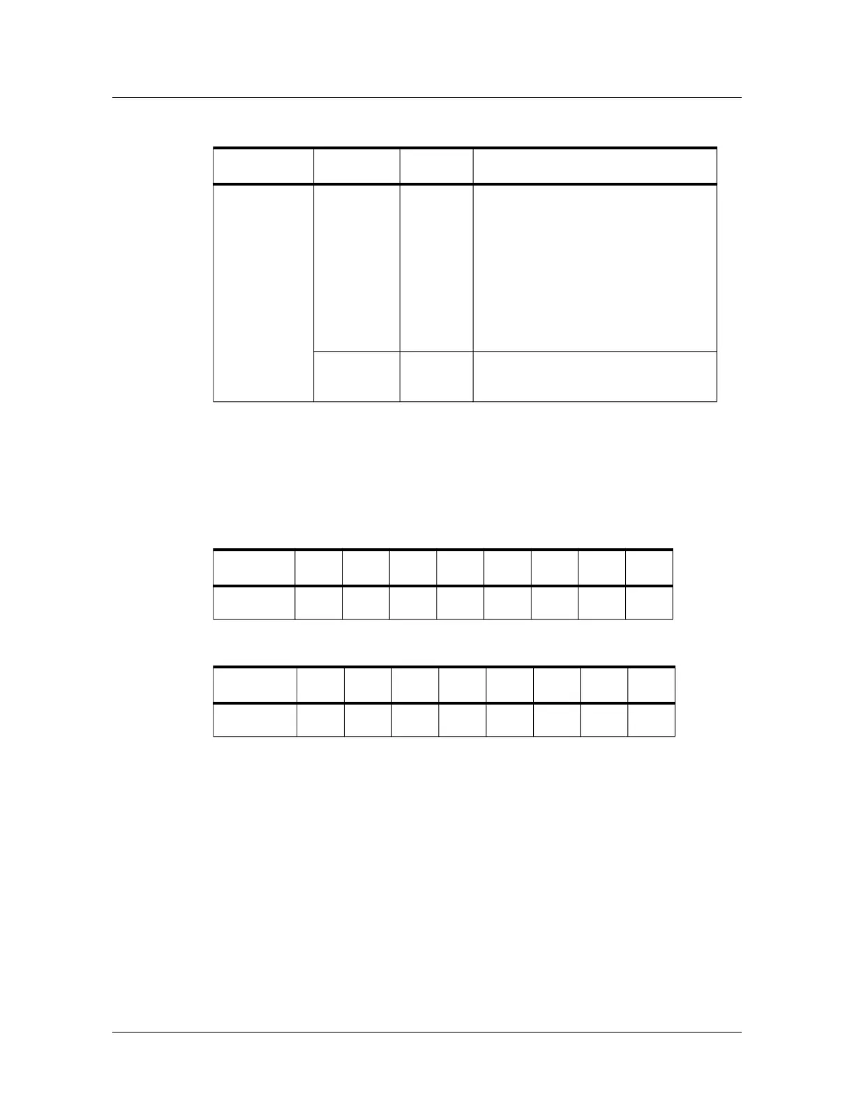
FLASH This is the processor heartbeat LED. It
flashes once every second. A short ON
time (~20% duty cycle) indicates the
board is offline or has lost serial
communication with the Controller
board. A long ON time (~80% duty
cycle) indicates the board is online and
communicating with the Controller
board.
FLASH Flash when there is activity on its Serial
Port.
Table 4: Relay LEDs: 0-7
RELAY # 0 1 2 3 4 5 6 7
LED D5 D6 D7 D8 D9 D10 D11 D12
Table 5: Relay LEDs: 8-15
RELAY # 8 9 10 11 12 13 14 15
LED D13 D14 D15 D16 D17 D18 D19 D20
Table 3: LED Settings
Mode LED D1 LED D2 Description
 Loading...