Installing the PRO4200 Output Module
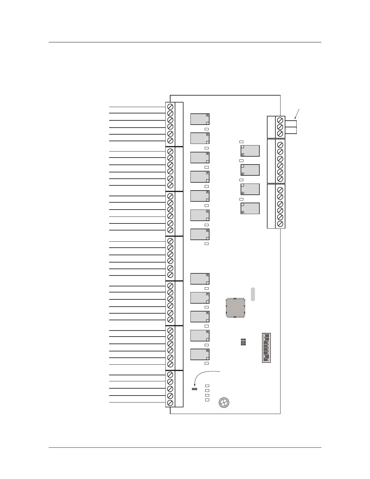
Wiring Diagram for Connectors 1 through 8
PRO4200 Output Module Installation Guide, Document 800-25697V1 17
Wiring Diagram for Connectors 1 through 8
Figure 1: PRO4200 Output Module Wiring: Connectors 1-8
DIP SWITCHES
ON
OFF
87654321
OUTPUT BOARD
Short
together*
Power
RS-485
RS-485 TR+
RS-485 TR-
RS-485 GND
+ 12V
GND
RELAY10 NO
RELAY10 C
RELAY10 NC
RELAY11 NO
RELAY11 C
RELAY11 NC
RELAY8 NO
RELAY8 C
RELAY8 NC
RELAY9 NO
RELAY9 C
RELAY9 NC
RELAY6 NO
RELAY6 C
RELAY6 NC
RELAY7 NO
RELAY7 C
RELAY7 NC
RELAY4 NO
RELAY4 C
RELAY4 NC
RELAY5 NO
RELAY5 C
RELAY5 NC
RELAY2 NO
RELAY2 C
RELAY2 NC
RELAY3 NO
RELAY3 C
RELAY3 NC
RELAY0 NO
RELAY0 C
RELAY0 NC
RELAY1 NO
RELAY1 C
RELAY1 NC
K 1 K 2 K 3 K 4 K 5 K 6 K 7 K 8 K 9 K 10 K 11 K 12
K 13 K 14 K 15 K 16
J 2
{
CardRack PWR &
Com Harness* (Rack
Mount
Only)
* Rack Mount Conguration
J 1 - RS-485
Termination
1
2
3
4
5
6
1
2
3
4
5
6
1
2
3
4
5
6
1
2
3
4
5
6
1
2
3
4
5
6
1
2
3
4
5
6
1
2
3
4
5
1
2
3
1
2
3
4
5
6
1
2
3
4
5
6
0
123456 7891011
D1 D2 D3 D4
D17 D18 D19 D20
 Loading...