18 www.honeywell.com
Installing the PRO4200 Output Module
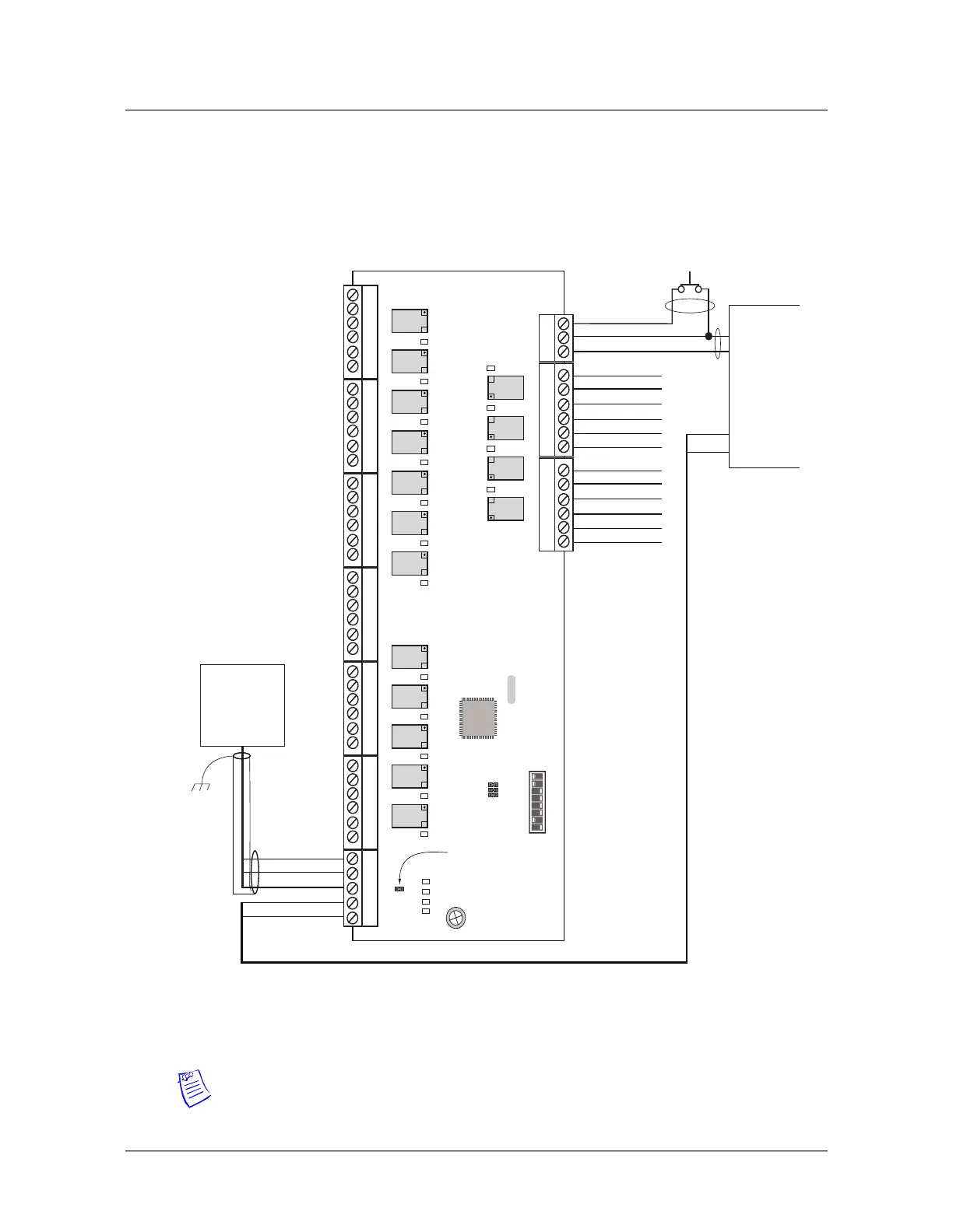
Wiring Diagram for Connectors 7 through 10
Wiring Diagram for Connectors 7 through 10
Figure 2: PRO4200 Output Module: Connectors 7-10
Note: For RS-485 Communication Connections, twist the blue pair together and use as
the common; use the orange pair as your data pair, observing polarity. Connect the
external drain shield to the appropriate earth ground on one end.
DIP SWITCHES
ON
OFF
87654321
16 OUTPUT BOARD
Power
RS-485
The connectors on
this side of the board
are not accessible
when it is rack
mounted.
RS-485 Com Bus
Cable From Dif.
Panel (Remote
Mount Only)
NC
Connect to
chasis GND at
one side
ONLY !
PWR +
PWR -
DC Output
+
_
+12VDC Power
C - No Charging
N/C - No Charging
Tamper Switch
(In CLOSED
position when
Cabinet Door is
Closed)
RS-485 TR+
RS-485 TR-
RS-485 GND
+ 12V
GND
K 1 K 2 K 3 K 4 K 5 K 6 K 7 K 8 K 9 K 10 K 11 K 12
K 13 K 14 K 15 K 16
J 1 - RS-485
Termination
J 2
1
2
3
4
5
6
1
2
3
4
5
6
1
2
3
4
5
6
1
2
3
4
5
6
1
2
3
4
5
6
1
2
3
4
5
6
1
2
3
4
5
1
2
3
1
2
3
4
5
6
1
2
3
4
5
6
TMP
GND
PFL
RELAY14 NC
RELAY14 C
RELAY14 NO
RELAY15 NC
RELAY15 C
RELAY15 NO
RELAY12 NC
RELAY12 C
RELAY12 NO
RELAY13 NC
RELAY13 C
RELAY13 NO
0
1 2 3 4 5 6 7 8 9 10 11
D1 D2 D3 D4
D17 D18 D19 D20
 Loading...