12 www.honeywell.com
Installing the PRO4200 Output Module
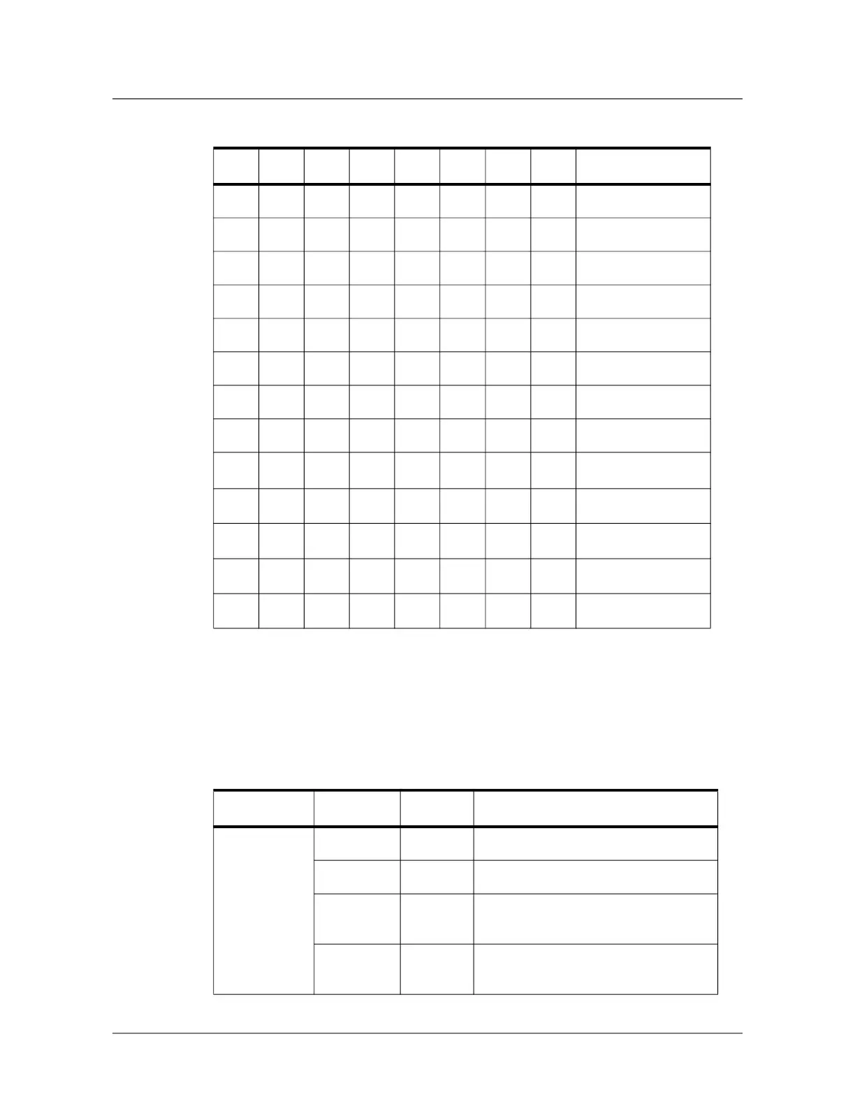
LED Operation
* = Default
LED Operation
The Output Board uses two onboard LEDs to provide status information during the
power-up sequence and during normal operation.
ON ON OFF OFF OFF ADDRESS 24
ON ON OFF OFF ON ADDRESS 25
ON ON OFF ON OFF ADDRESS 26
ON ON OFF ON ON ADDRESS 27
ON ON ON OFF OFF ADDRESS 28
ON ON ON OFF ON ADDRESS 29
ON ON ON ON OFF ADDRESS 30
ON ON ON ON ON ADDRESS 31
OFF OFF
Reserved
OFF ON
9,600 BPS
ON OFF
19,200 BPS
ON ON
38,400BPS*
OFF
Not Used*
Table 2: PRO4200 Output Module DIP Switch Settings (continued)
S8 S7 S6 S5 S4 S3 S2 S1 Selection
Table 3: LED Settings
Mode LED D1 LED D2 Description
Power-up
sequence
ON OFF Start power-up, hardware setup
OFF ON Testing RAM
ON ON Testing ROM and completing
initialization
FLASH ON LED D1 flashes 4 times after power-up
is completed
 Loading...