C7012A,C,E,F,G SOLID STATE PURPLE PEEPER® ULTRAVIOLET FLAME DETECTORS
60-2398-17 6
Screening Effects
Smoke, oil mist, dirt and dust are masking agents that
attenuate the ultraviolet radiation that the flame emits. If they
absorb too much radiation, the amount of ultraviolet radiation
reaching the detector is reduced. The flame signal then can
become too low to hold in the flame relay, resulting in burner
shutdown.
Diluting the contaminants can eliminate the problem. A strong
flow of air through the sight pipe clears a viewing path through
the attenuating material. Refer to the Sight Pipe Ventilation
section.
It is also desirable to sight the detector in an area containing
fewer masking agents such as near the burner nozzle or near
the entrance of the combustion air. Increasing the viewing area
of the detector by shortening the sight pipe or by increasing the
diameter of the sight pipe also reduces the attenuating effects
of masking agents.
Multiburner Requirements
(Flame Discrimination)
In addition to meeting the requirements for a single burner, a
multiburner installation requires discrimination between flames.
Flame discrimination can be defined as locating all flame
detectors so that each detector responds only to the flame of
the burner it is supervising.
In multiple burner systems, not every detector can be
positioned so its line-of-sight does not intercept flames from
other burners. For example, this situation occurs in front-fired
boiler-furnaces having more than one row of burners, or in
multilevel opposed-fired furnaces where the burners face each
other.
When planning such an installation, locate each flame detector
so that it has the best possible view of the first
30 percent closest to the burner nozzle (the flame root) it is
supervising, and the worst possible view of all other flames.
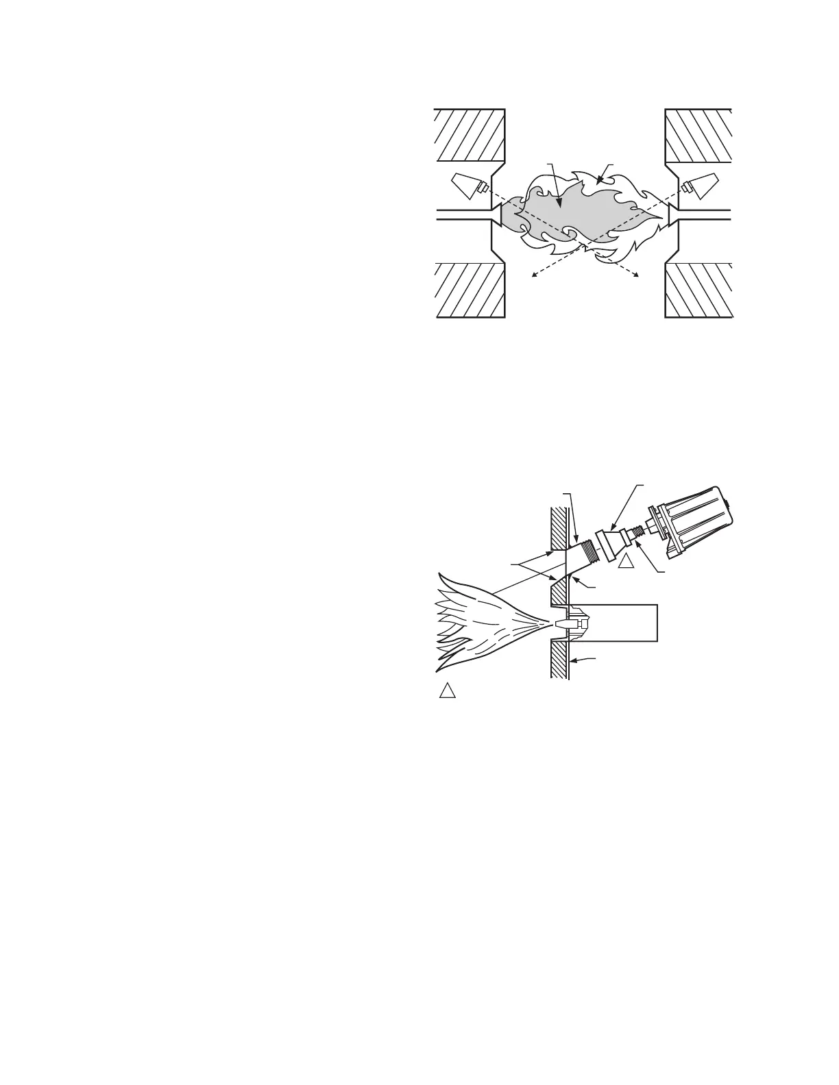
Fig. 4 illustrates a critical detector application problem that
requires flame discrimination. Flame discrimination is
accomplished for Detector A by repositioning it until the flame
relay (in the flame safeguard control) does not respond to
Flame B. Note that Detector A is aimed at the first 30 percent
of Flame A where the ultraviolet radiation is most intense.
It sights the tip of Flame B, but it is not aimed at the first
30 percent of Flame B where UV is intense. Detector A is
repositioned to assure maximum response to Flame A while
rejecting Flame B. Similarly, Detector B is positioned to assure
maximum response to Flame B while rejecting Flame A.
If you reposition a detector and still cannot achieve flame
discrimination, try reducing the viewing area by increasing the
length or decreasing the diameter of the sight pipe, or adding
an orifice plate.
Install the Sight Pipe (Fig. 5)
After you have determined the location and sighting angle,
select the sight pipe. A black iron pipe with a diameter of at
least 1-1/2 in. (38 mm) is recommended. Do not use stainless
steel or galvanized pipe because they reflect ultraviolet
radiation internally and complicate aiming the pipe.
Fig. 4. Example of flame discrimination
problem (opposed-fired burners).
Sight pipes with diameters 2 to 3 in. (51 to 76 mm) produce
better results for horizontal rotary burners, which require wide
viewing angles. A wide viewing angle can also be obtained by
using a short sight pipe.
Fig. 5. Typical mounting of C7012.
Prepare Hole in Combustion
Chamber Wall
Cut or drill a hole of the proper diameter for the sight pipe in the
wall of the combustion chamber at the selected location. Flare
the hole to leave room for small adjustments of the sighting
angle. The taper of the hole should be about 1 in. for every 3
in. (25 mm for every 76 mm) of wall thickness.
Mount Sight Pipe
Thread one end of the pipe to fit the mounting flange, union, or
required coupling. Cut the pipe to the desired length (as short
as practical) and at an angle so it fits flush with the wall of the
combustion chamber. Tack weld the pipe to the wall in a trial
position. Do not weld the sight pipe permanently in place until
after completing the Adjustments and Checkout procedures.
M1957
DETECTOR A
FLAME A
DETECTOR B
FLAME B
1
CLOSE NIPPLE
(3/4 in. FOR
A C7012E; 1 in.
FOR A C7012F.
TEMPORARY
TACK WELD
COMBUSTION
CHAMBER WALL
REDUCER
BLACK IRON SIGHT
PIPE (1-1/2 TO 3 in.
[38 TO 76 mm] DIA.)
REFRACTORY
FLARED
HOLE
1
IF VENTILATION OF THE SIGHT PIPE IS REQUIRED, ADD PIPE
TEE, PERFORATED NIPPLE, OR OTHER SUITABLE DEVICE
FOR VENTILATION.
M6814

 Loading...