C7012A,C,E,F,G SOLID STATE PURPLE PEEPER® ULTRAVIOLET FLAME DETECTORS
7 60-2398-17
NOTE: If you use 118367A Swivel Mount and you are
positive about the location and sighting angle, you
can permanently weld the pipe.
Install Fittings
In some cases, the sight pipe will not directly fit the C7012
mounting flange or union. Also, it may be desirable or
necessary to ventilate the sight pipe. You may also want to use
a swivel mount or an antivibration mount. Each of these cases
can require additional fittings.
Reducer
For sight pipes of larger diameter than the mounting flange
connector or union, install a reducer as illustrated in Fig. 5. The
reducer requires a close nipple with these external threads:
C7012A or E: 3/4 or 1 in. NPT (depending on model).
C7012C or F: 1 in. NPT.
C7012G: 3/4 in. NPT.
Sight Pipe Ventilation (C7012A,E, or
G)
It may be necessary to ventilate the sight pipe to cool the
detector or to clear a viewing path through UV radiation
attenuating material.
For a negative pressure combustion chamber, drilling a few
holes in the section of the sight pipe outside of the combustion
chamber allows air at atmospheric pressure to flow through the
sight pipe and into the chamber. A perforated pipe nipple
between the sight pipe and the detector can also be used.
For a positive pressure combustion chamber, connect a supply
of pressurized air from the burner blower to flow through the
sight pipe and into the chamber. The air pressure must be
greater than the chamber pressure.
Antivibration Mount (C7012A,E, or G)
The detector can withstand normal burner vibration. If the
vibration is excessive, part no. 123539 Antivibration Mount is
available for a C7012A,E or G. (For mounting details, see form
60-0361.) If you use this mount, install it before positioning and
sighting the detector.
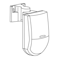
Mount the Detector (Fig. 5-8)
Mount the detector onto the sight pipe, reducer, or other fitting
(see Fig. 5-8).
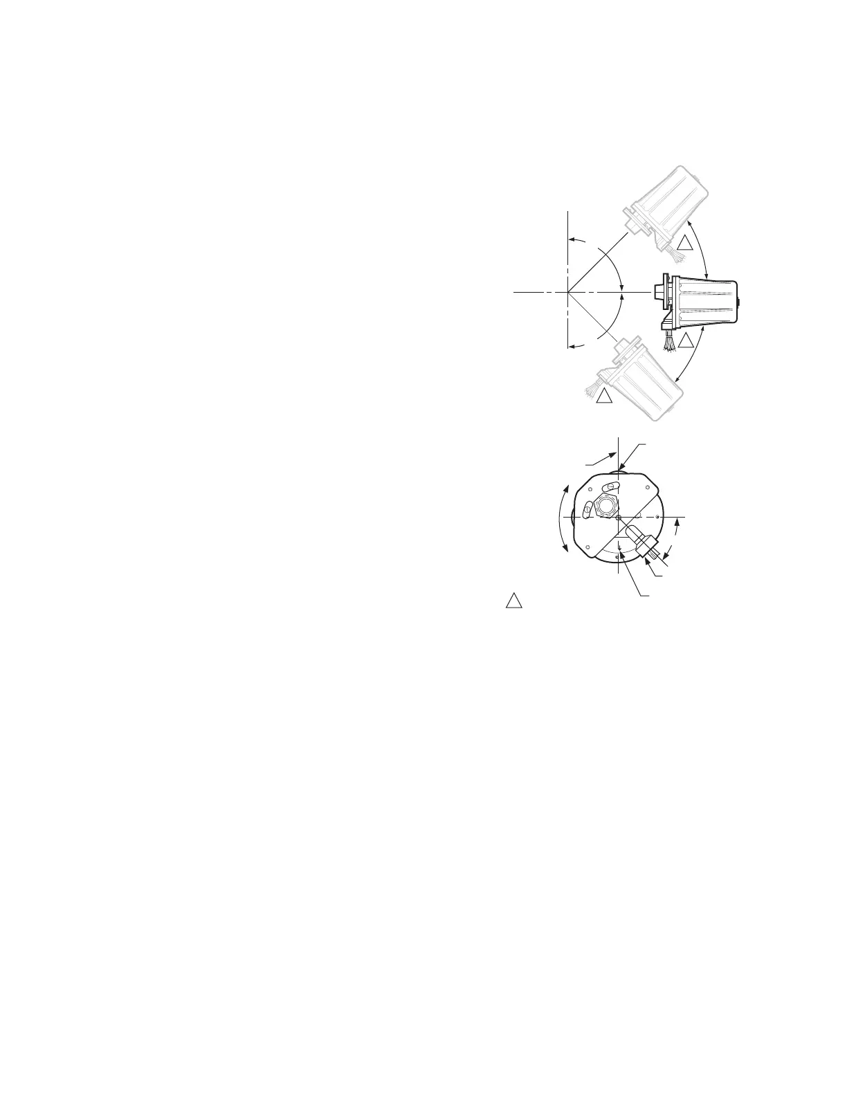
The C7012A,C,G Flame Detectors do not have the oscillating
shutter mechanism for checking the UV sensor so they can be
mounted in any position suitable for the temperature
environment.
The C7012E,F Self-Checking Flame Detectors incorporate an
oscillating shutter mechanism and, therefore, require special
consideration for mounting positions other than vertically
sighting downward or upward. The C7012E has notch and
arrow indicators (see Fig. 6) on the faceplate to facilitate
mounting. The notch and arrow must be vertically aligned with
the notch in the up position and the arrow pointing downward
(see Fig. 6). The C7012F must be mounted with the conduit
opening located approximately 45 degrees below the
horizontal (see Fig. 6).
Fig. 6. C7012E,F mounting positions.
IMPORTANT
The notch and arrow on the faceplate of the C7012E
must be aligned in a vertical plane with the notch up
and the arrow pointing downward.
The C7012F housing must be mounted with the
conduit opening approximately 45° below horizontal
(see Fig. 6).
To mount a C7012A,E or G (Fig. 7):
1. The mounting flange has two pieces. Loosen (but do not
remove) the three screws holding the flange together.
2. Slightly rotate the detector so the slots in the back
section of the mounting flange clear the screws in the
front section; then separate the two sections.
3. Screw the front section of the mounting flange onto the
sight pipe, reducer, or other fitting.
4. Fit the slots in the back section of the mounting flange
(with the detector) over the three screws in the front sec-
tion, and rotate the detector so the screws hold the
flange together.
5. Tighten the screws securely.
M6816
C7012E, F CAN BE MOUNTED
HORIZONTALLY, VERTICALLY, OR
AT ANY ANGLE IN BETWEEN
HORIZONTZAL
PLANE
VERTICAL
PLANE
90
90
1
1
1
NOTCH IN FACEPLATE
MUST BE UP
HORIZONTZAL
PLANE
NOTCH AND ARROW
MUST ALWAYS BE
ALIGNED IN A
VERTICAL PLANE
C7012E OR F
MUST NOT
BE ROTATED
AROUND
ITS AXIS
ARROW ON FACEPLATE
MUST BE POINTING
DOWNWARD
45
C7012F CONDUIT
OPENING POSITION
ADE IN U.S.A.
MOUNT WITH
ARROW DOWN
1
NOTE DOWNWARD
POSITIONING OF
CONDUIT OPENING.

 Loading...