C7012A,C,E,F,G SOLID STATE PURPLE PEEPER® ULTRAVIOLET FLAME DETECTORS
60-2398-17 8
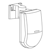
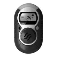
Fig. 7. Mounting C7012A, E, or G Detector.
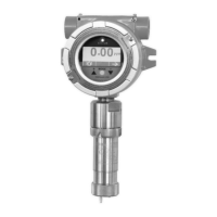
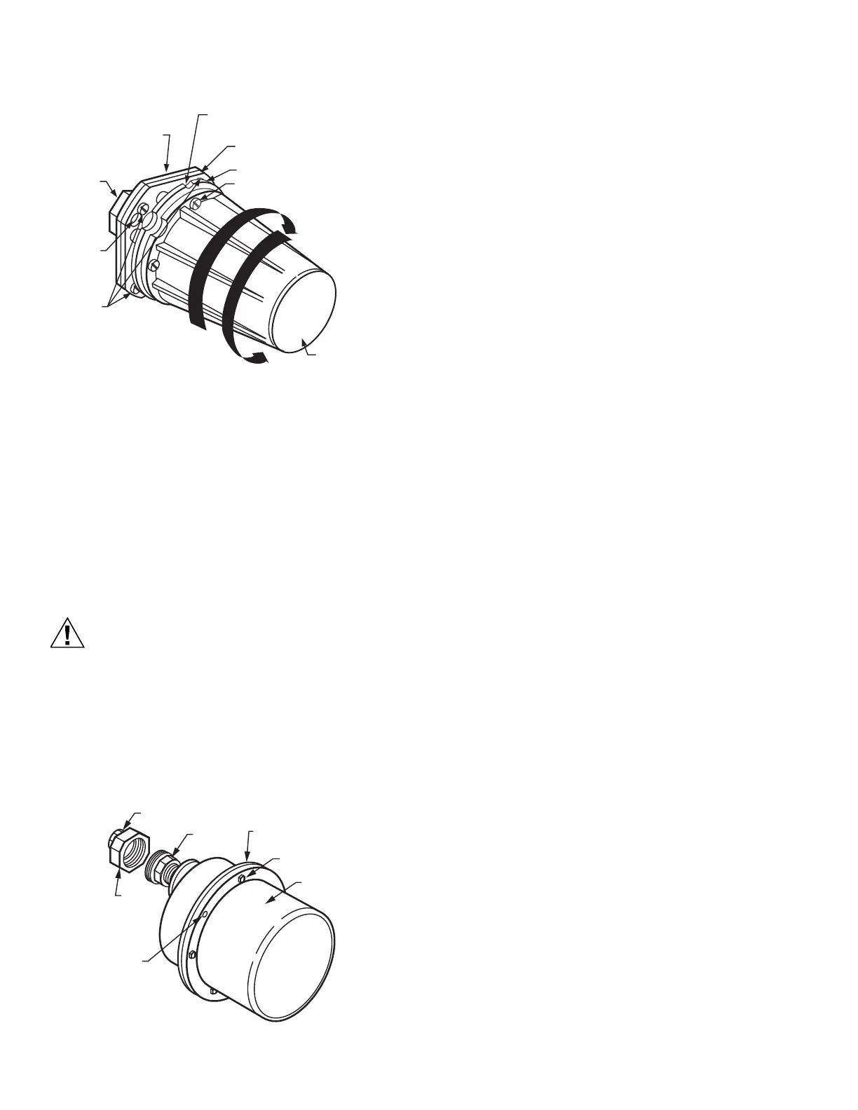
To mount a C7012C or F with explosion-proof housing (Fig. 8):
1. Unscrew the collar on the pipe union and remove the
coupling section. The collar and coupling are in two
pieces; do not separate them.
2. Screw the coupling onto the sight pipe, reducer, or other
fitting.
3. Mount the remainder of the pipe union (with the detector)
onto the coupling and securely tighten the collar.
Wiring (Fig. 9-16)
Equipment Damage Hazard.
Improper wiring can permanently damage
amplifier.
When using a C7012E or F with an R7247C, R7847C
Dynamic Self-Check Amplifier, be careful not to short
the white shutter leadwires together (by wiring
incorrectly, leaving an incorrect jumper wire, or
stripping the insulation too much so the bare leadwires
can touch).
Fig. 8. Mounting C7012C or F Detector.
IMPORTANT
Certain C7012E and all G models are designed to
meet DIN and BGC requirements. They have an addi-
tional yellow/green grounding leadwire; connect this
wire to a separate ground terminal on the wiring sub-
base.
1. All wiring must comply with applicable local electrical
codes, ordinances and regulations.
NOTE: The detector has color-coded and labeled, plastic
insulated, no. 18 leadwires, 8 feet (2/4 m) long, rated
for 221°F (105°C).
2. Keep the flame signal leadwires as short as possible
from the flame detector to the terminal strip or wiring
subbase.
NOTE: Capacitance increases with leadwire length, reducing
the signal strength. The maximum permissible
leadwire length depends on the type of leadwire,
conduit type and diameter. The ultimate limiting factor
in flame signal leadwire length is the signal current or
voltage at the flame safeguard device. Refer to Table
1.
3. Detector leadwires can be spliced for longer leadwire
runs, observing the following considerations (see Fig. 9):
a. Make required splices in a junction box.
b. Use moisture-resistant no. 14 wire suitable for at
least 167°F (75°C).
c. For high temperature installations, use Honeywell
specification No. 32004766-003 or equivalent for the
F leadwire. This wire is rated up to 400°F (250°C) for
continuous duty. It it tested for operation up to 20,000
volts and for breakdown up to 32,000 volts. For the
other leadwires, use moisture-resistant no. 14 wire
selected for a temperature rating above the maxi-
mum operating temperature.
d. F and G wires (blue and yellow) must be run in their
own conduit independent of other power carrying
leadwires. More than one set of scanner F and G
wires can be run in the same conduit.
e. A shielded twisted pair wire may be substituted for
conduit for routing the F leadwire (blue). Be advised
of the capacitance per foot of shielded wire effec-
tively reduces the flame signal at the flame safe-
guard device. Be sure to ground the shield to the G
terminal at the flame safeguard wiring subbase.
f. The detector power and shutter wires need to be run
in their own conduit as well, avoiding other electrical
noise carrying wiring.
g. The scanner wires should remain separated a mini-
mum of 2 inches from other line voltage wires in the
main control panel to the flame safeguard device.
4. The following installation considerations can influence
detector operation and maximum leadwire length and
should be avoided:
a. Moisture.
b. Ignition interference.
c. high resistance connections or poor grounds.
d. Leadwire capacitance.
e. Voltage fluctuations.
f. Induced line transients.
g. Floating grounds—ground at some voltage above
earth ground.
h. No G wire—burner used as ground.
i. Detector output less than maximum attainable for the
installation (inadequate sighting).
5. Refer to Fig. 10 through 17 for wiring connections.
ROTATE DETECTOR THIS
WAY WHEN MOUNTING
NOTCH IN FACEPLAGE
(C7012E ONLY)
ROTATE
DETECTOR
THIS WAY TO
SEPARATE
MOUNTING
FLANGE
SCREW ONTO
SIGHT
PIPE
SLOT (3)
M24002
COVER
FACEPLATE
FLANGE
SCREWS (3)
BACK SECTION OF
MOUNTING FLANGE
CAPTIVE COVER
SCREWS (4)
124198 (1 IN. NPT) SHOWN
FRONT SECTION OF
MOUNTING FLANGE
COVER
HEX-HEAD
COVER BOLT (6)
BODY FLANGE
PIPE
UNION
COLLAR
SCREW COUPLING
ONTO SIGHT PIPE
HOLE
KEYED
TO PIN
ON BODY
FLANGE
M1955

 Loading...