EasyManua.ls Logo

Honeywell PW7000 Series - User Manual

Honeywell PW7000 Series
26 pages
Print Icon
To Next Page IconTo Next Page
Loading...
March 2021 © 2020 Honeywell. All rights reserved. 800-26498
PW7K1R1E
OSDP Reader Interface
Installation and Configuration Guide
Question and Answer IconNeed help?

Do you have a question about the Honeywell PW7000 Series and is the answer not in the manual?

Summary

Introduction to PW7 K1 R1 E Reader Interface

Overview of PW7 K1 R1 E Functionality

Describes the PW7K1R1E reader interface, its network connectivity, and capabilities for controlling two physical barriers with OSDP readers.

Warranty Information for Honeywell Security Access Products

Details the one-year warranty for material and workmanship defects under normal use and service for Honeywell Security Access products.

Product Liability and Usage Restrictions

Outlines liability regarding product usage for controlling exits and states it's not intended for life-critical applications.

CE and WEEE Marking Compliance

Explains the CE standard logo and WEEE symbol indicating compliance with EU regulations and product recycling.

FCC Compliance Statement

Provides the FCC compliance statement, detailing conditions for operation and avoiding harmful interference.

PW7 K1 R1 E Wiring and Setup Guide

PW7 K1 R1 E Hardware Components

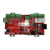
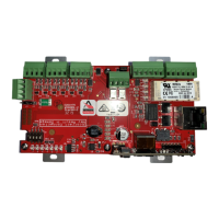
Identifies and illustrates the key hardware components of the PW7K1R1E control board, including ports and connectors.

Terminal Connections for PW7 K1 R1 E

Details the terminal connections on the PW7K1R1E board, specifying acronyms and their descriptions for inputs, outputs, and power.

Jumper Configuration Settings

Explains the function of each jumper on the PW7K1R1E, including settings for power source and factory use.

DIP Switch Configuration Modes

Describes the operating modes configurable via the four DIP switches on the PW7K1R1E, including normal and special modes.

Factory Default Communication Parameters

Lists the default network settings, including IP address, subnet mask, and default gateway for the PW7K1R1E.

Bulk Erase Functionality

Explains the purpose of the bulk erase function, which sanitizes the board and restores OEM default parameters.

Steps for Performing Bulk Erase

Provides step-by-step instructions on how to perform the bulk erase operation on the PW7K1R1E.

Input Power Options for PW7 K1 R1 E

Details the two methods of powering the PW7K1R1E: via Ethernet using PoE or PoE+, or via a local 12VDC power supply.

Communication Wiring Standards

Specifies the communication method between the controller and PW7K1R1E as Ethernet (10Base T/100Base-TX).

OSDP Reader Wiring and Power

Covers wiring for OSDP readers using RS-485 communication and 12 VDC power, supporting up to four readers.

Input Circuit Wiring Configurations

Explains how input circuits are used for monitoring door status, request to exit, or alarm contacts, supporting supervised and unsupervised modes.

Relay Circuit Wiring for Control

Details the use of four Form-C relays for controlling door locks or alarm signaling, rated at 2A @ 30VDC.

Status LED Indicators and Meanings

Describes the function and behavior of the status LEDs on the PW7K1R1E during power-up and normal operation.

IT Security Best Practices for Installation

Provides guidance on secure installation practices, including password creation and DIP switch settings for the PW7K1R1E.

Technical Specifications of PW7 K1 R1 E

Lists detailed technical specifications for power input/output, reader interface, inputs, communication, and cable requirements.

Additional Mounting Information and Options

Provides details on optional mounting accessories, such as blank covers and junction boxes, and their part numbers.

Important Warnings for Product Use

Contains warnings related to product handling, installation, and warranty, reiterating limitations and return procedures.

Product Liability and Usage Limitations

Reiterates liability restrictions, emphasizing that the interface is not for life-critical applications and misuse voids liability.

Overview

The PW7K1R1E is a network-connected OSDP Reader Interface designed for integrating TTL/RS-485 type readers with door hardware in access control systems. This device provides a PoE-based solution for two doors with paired readers, enabling easy installation through its on-board twisted pair Ethernet jack with PoE support.

Function Description:

The PW7K1R1E allows for the control of two physical barriers, supporting single or paired readers. Its OSDP reader port can accommodate up to four read heads, utilizing 2-wire RS-485 electrical signaling standards. It also supports one or two-wire LED controls and buzzer control (in one-wire LED mode only). The device features four form-C relay outputs for door strike control or alarm signaling, rated at 2A @ 30VDC in a dry contact configuration. Six inputs are provided for monitoring door contacts, exit push buttons, and alarm contacts. Communication between the controller (PW7101 or PW7000) and the PW7K1R1E is via Ethernet (10Base T/100Base-TX), with built-in and automatic encryption. It is not recommended to connect the PW7K1R1E to a public intranet.

Important Technical Specifications:

Power:

  • Input:
    • PoE Power Input: 12.95W, compliant with IEEE 802.3af.
    • PoE+: 25W, compliant with IEEE 802.3at.
    • Local 12VDC Power Supply: 12VDC ±10%, 1.7A maximum.
  • Output:
    • PoE: VO (TB4-1) and RVO (TB7-4), combined: 12VDC @ 0.66A maximum PoE+.
    • 12VDC: VO (TB4-1) 12VDC @ 1A maximum, RVO (TB7-4) 12VDC @ 0.5A maximum.
  • Reader Power (TB7-4 / RVO): 12VDC @ 0.5A maximum.
  • Relays: Four Form-C contacts, rated at 2A @ 30VDC.
  • Inputs: Six unsupervised/supervised inputs, End of Line resistors: 1k/1k ohm, 1%, ¼ watt (Standard).

Communication:

  • Ethernet: Category 5 minimum cable.
  • RS-485 Mode:
    • 2-Wire RS-485, OSDP protocol, four devices maximum.
    • 9600 bps, Asynchronous, Half-duplex.
    • 1 start bit, 8 data bits, 1 stop bit.
    • Maximum cable length: 4000' (1,200m).

Wiring:

  • Power: 18 AWG, 1 twisted pair.
  • RS-485: 24 AWG, 120-ohm impedance, 4,000ft (1,220m) maximum. Twisted pair(s) with an overall shield, 18 AWG.
  • Alarm Input: Twisted pair per input, 30-ohm maximum loop resistance.
  • Reader Data (RS-485): 24 AWG, 120-ohm impedance. Twisted pair with shield, 4000-foot (1220m) maximum, 18 AWG*.

Environmental:

  • Storage Temperature: -55°C to +85°C.
  • Operational Temperature: 0°C to +70°C.
  • Humidity: 5 to 95% RHNC.

Mechanical:

  • Dimensions (without bracket): 5.5" (140mm) W x 2.75" (70mm) L x 0.96" (24mm) H.
  • Dimensions (with bracket): 5.5" (140mm) W x 3.63" (92mm) L x 1.33" (34mm) H.
  • Weight (without bracket): 4 oz. (112g).
  • Weight (with bracket): 5 oz. (142g).

UL294 Performance Levels:

  • 6th edition
  • Stand by Power: I
  • Endurance: IV
  • Line Security: I
  • Destructive Attack: I

Usage Features:

  • Power Options: The PW7K1R1E can be powered via PoE/PoE+ from the Ethernet connection or by a local 12VDC power supply. Jumper J5 is used to select the power source.
  • Scalability: A maximum of 16 PW7K1R1E downstream boards can be connected to a PW7K1ICE controller board.
  • OSDP Reader Support: The OSDP reader port on TB7 provides connections for the 2-wire RS-485 OSDP communication bus and 12VDC to power OSDP readers. Up to four OSDP readers are supported.
  • RS-485 Termination: Jumper J4 is installed only if the PW7K1R1E is at one end of the communication bus. Termination should only be applied to devices at each end of the bus, not more than two devices.
  • Input Circuit Configuration: Inputs can be configured as unsupervised (reporting open or closed states) or supervised (reporting open circuit, shorted, grounded, and foreign voltage). Supervised circuits require two 1K Ohm, 1% resistors located close to the sensor.
  • Relay Circuit Usage:
    • Normally Open (NO) and Common (C) poles are used for controlling power to the door strike.
    • Normally Closed (NC) and Common (C) poles are used for momentarily removing power to unlock a mag lock.
  • DIP Switch Configuration (S1): Four switches are used to configure the operating mode, including normal operation, enabling default user credentials, using factory default communication parameters, using OEM default communication parameters, and entering Bulk Erase prompt mode.
  • Status LEDs: LEDs provide visual feedback on the device's status, including on-line/off-line status, encryption status, host communication, data reception from readers, and input status (inactive, active, fault). J1-YELLOW and J1-GREEN LEDs indicate Ethernet speed and link/activity.

Maintenance Features:

  • Bulk Erase Function: This feature allows for erasing all configuration, setting the PW7K1R1E to OEM settings (sanitizing the board), or restoring to OEM default parameters. The process involves specific DIP switch settings and power cycling.
  • IT Security: Upon installation, it is crucial to create secure user accounts for the web configuration page and ensure all DIP switches are in the OFF position for normal operating mode. The default login account (admin/password) is enabled when DIP 1 is ON for five minutes, during which at least one user account should be defined. It is highly recommended not to configure the PW7K1R1E with an IP address accessible from the public Internet. Options to disable Zeroconf discovery and the web configuration module are available to enhance network security.
  • Relay Protection: To prevent damage and premature failure of relays from feedback generated by door lock mechanisms, it is recommended to use either a diode or MOV (metal oxide varistor) to protect the relay.
  • Warranty: Honeywell Security Access provides a one-year warranty against defects in material and workmanship under normal use and service. The warranty is limited to repair or replacement of defective units. Returns require a Returned Merchandise Authorization (RMA) number.

Honeywell PW7000 Series Specifications

General IconGeneral
BrandHoneywell
ModelPW7000 Series
CategoryRecording Equipment
LanguageEnglish

Related product manuals