EasyManua.ls Logo

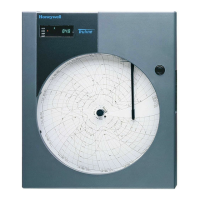
Honeywell DR4500A User Manual

Honeywell DR4500A
266 pages
To Next Page IconTo Next Page
Page #1 background imageLoading...
Page #1 background image
Honeywell Field Solutions
DR4500A Classic Series Circular Chart
Recorder With or Without Control
Product Manual
Doc. No.: 44-45-25-35
Release: M
Last Revision Date: April 2017

Table of Contents

Questions and Answers:

Honeywell DR4500A Specifications

General IconGeneral
ModelDR4500A
Power Supply100-240 VAC, 50/60 Hz
Operating Temperature0 to 50°C (32 to 122°F)
Input TypeThermocouple, RTD, mV, V, mA
Chart Size10 inch (254 mm)

Summary

2. Installation

2.5 Wiring Prerequisites

Outlines precautions and requirements for electrical wiring and grounding.

2.6 Input Wiring Procedures

Provides instructions for wiring the recorder's inputs based on model number.

2.7 Output Wiring Procedures

Provides instructions for wiring the recorder's outputs.

3. Configuration

3.6 Input Set Up Group

Parameters for configuring recorder inputs 1 and 2.

3.10 Control Set Up Group

Parameters for controlling the process and recorder functions.

3.11 Tuning Parameters Set Up Group

Parameters for adjusting tuning constants for optimal response.

3.14 Alarms Set Up Group

Parameters for configuring the recorder's alarm functions.

3.18 Lockout Set Up Group

Parameters to prevent unauthorized changes to configuration and calibration.

4. Configuration Parameter Definitions

4.2 Input Parameters Set Up Group

Definitions for parameters related to recorder inputs 1 and 2.

4.6 Control Parameters Set Up Group

Definitions for parameters controlling process and recorder functions.

4.7 Tuning Parameters Set Up Group

Definitions for parameters adjusting tuning constants for optimal response.

4.10 Alarms Set Up Group

Definitions for parameters related to alarm functions.

4.14 Lockout Parameters Set Up Group

Definitions for parameters to prevent unauthorized changes.

5. Operation

5.4 Monitoring Your Recorder

How to monitor recorder indicators, displays, and error messages.

5.5 Operator Functions

Actions an operator can initiate on the recorder.

5.7 Setpoints

Procedures for configuring and changing setpoints.

5.9 Using Two Sets of Tuning Constants (PID Values)

Procedure for using and switching between two sets of PID tuning constants.

5.11 Alarm Setpoints

Procedure for displaying and changing alarm setpoints.

6. Setpoint Ramp/Soak Programming and Operation

Entering the Setpoint Program Data

Procedure for entering setpoint program data using the keypad.

SP RAMP1 and SP RAMP2 Set Up Group

Prompts for configuring setpoint ramps for control loops 1 and 2.

Run/Monitor the Program

Instructions for running, monitoring, holding, and ending setpoint programs.

7. Input Calibration

Calibration Set Up and Wiring for PV Inputs

Details jumper positions and wiring for PV input calibration.

Calibration Procedure

Step-by-step procedure for calibrating all input types.

8. Output Calibration

Current Proportional Output/Aux Out 2 and 3 Calibration

Procedure for calibrating current proportional and auxiliary outputs.

Position Proportional Output Calibration

Procedure for calibrating position proportional output control.

Auxiliary Output Calibration

Procedure for calibrating the auxiliary output.

9. Troubleshooting / Service

Self Diagnostics

Details power-up tests and error messages for system diagnostics.

Related product manuals