Installation - Wiring Prerequisites
28 DR4500A Classic Series Circular Chart Recorder With or Without Control Product Manual Release M
April 2017
For the RS485 Modbus communications cable, Alpha XTRA Guard I cable (Alpha P/N 5121C) is required.
At the recorder end, the communications cable shield must be unconnected and must not extend into the
recorder enclosure. The shield of the communications cable must be connected to earth ground at the
farthest end of the cable. See the option wiring procedure for the RS485 Communications Card.
Inside of the enclosure, the user must install ferrite suppression filters and capacitors on all wires connected
to the recorder. ©Fair-Rite Products Corp. part number 0443164151, or equivalent, shall be installed as
shown in Figure 2-11 to Figure 2-22, one filter for each circuit group.
Cable with an outer jacket diameter larger than 6.7 mm (0.264 in.) may require the outer jacket to be
removed to fit the required one turn in the filter, or the selection of a different cable.
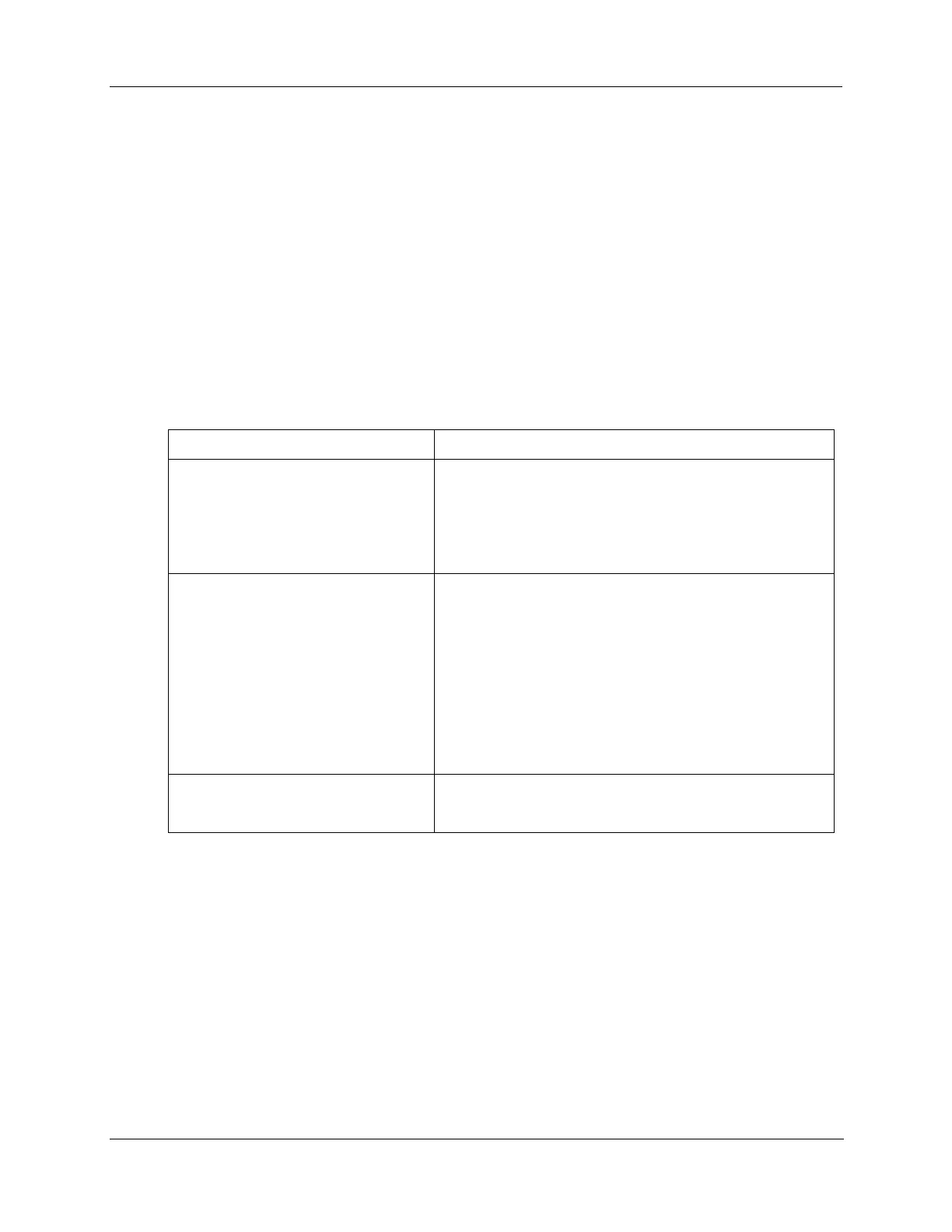
Permissible wire bundling
Table 2-10 shows which wire functions should be bundled together.
Table 2-10 Permissible wiring bundling
Earth ground wiring
Control relay output wiring
Line voltage alarm wiring
Analog signal wire, such as:
Input signal wire (thermocouple, 4 to 20 mA, etc.)
4-20 mA output signal wiring
Slidewire feedback circuit wiring
Digital input signals
Communications
4-20 mA auxiliary output
Low voltage alarm relay output wiring
Low voltage wiring to solid state type control circuits
Identify your wiring requirements
To determine the appropriate diagrams for wiring your recorder, refer to the model number interpretation in
this section. The model number of the recorder can be found on the chart plate.