Configuration Parameter Definitions
Auxiliary Output Set Up Group
Release M DR4500A Classic Series Circular Chart Recorder With or Without Control Product Manual 109
April 2017
4.11 Auxiliary Output Set Up Group
Introduction
This provides a milliampere output representing any of twelve control parameters: Input 1-2, PV 1-2,
Deviation 1-2, Output 1-2, Setpoint 1-2. The display for auxiliary Output viewing will be in engineering
units for all but output. Output will be designated in percent (%).
Timer group prompts
Table 4-11 lists all the function prompts in the Auxiliary Output setup group and their definitions.
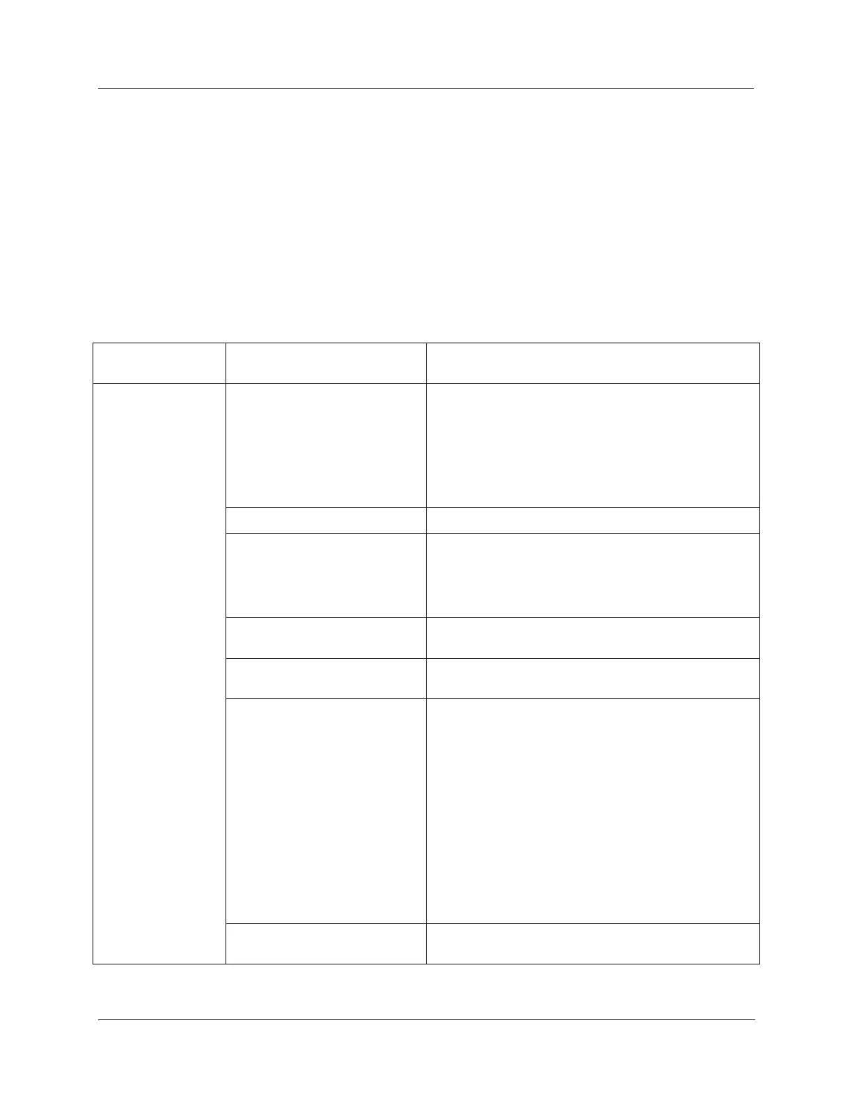
Table 4-11 Auxiliary output group definitions
Upper Display
Range of Setting or Selection
AUXILIARY OUTPUT SELECTION provides an mA
output representing any of twelve control parameters.
The display for Auxiliary Output viewing will be in
engineering units for all but output. Output will be
designated in percent (%).
Other prompts affected by these selections:
“4 mA VAL” and “20mA VAL”.
INPUT 1—This represents the configured range of input
1. FOR EXAMPLE:
Type “J” Thermocouple (0 to 1600°F)
0°F display = 0% output
1600°F display = 100% output
INPUT 2—This represents the value of the configured
range of input 2.
PROCESS VARIABLE 1—Represents the value of the
Process Variable for Loop 1. PV = Input 1 + Bias
DEVIATION 1 (PROCESS VARIABLE MINUS
SETPOINT)—Represents –100 to +100% of the
selected PV span in engineering units for Loop 1.
FOR EXAMPLE:
Type “T” Thermocouple
PV range = –300 to +700°F
PV span = 1000°F
Deviation range = –1000 to +1000°F
If PV = 500°F
and SP = 650°F
then Deviation Display = –150°F
Auxiliary Output = 42.5%
NOTE: A deviation of 0°F yields an auxiliary output of
50%.
OUTPUT 1—Represents the displayed controller output
in percent (%) for Loop 1.