#2 #1
22083
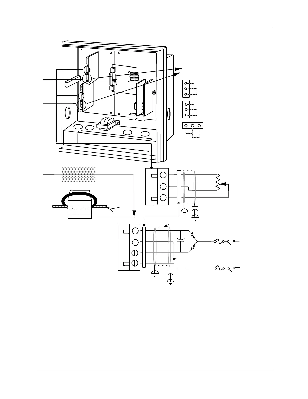
Control
output
#1
PCB
Control
output
#2
PCB
Control output
#1-2 PCB
Relay No. 1
W2 = N.O. contact
W3 = N.C. contact
Relay No. 2
W4 = N.O. contact
W5 = N.C. contact
W5
W4
W3
W2
W6
W7
W6 = Position
Proportional
Output
Fair-Rite P/N 0443164151
or equivalent
Ferrite Filter
1
2
3
Plug J2
OPEN
CLOSED
Motor's feedback
slidewire 100ž
to 1000ž
(Not required for
Three Position
Step Control)
Plug J5
N
H
Motor
power
supply
CLOSED (CCW)
OPEN (CW)
Capacitor Kit 51197755-001
Install capacitors as shown in figure.
Required for CE Mark Conformity
Kit Part No. 51197612-502, contains
two ferrite filters; Part No.
51197612-508 contains 8 ferrite filters.
Install inside of case. See Figure 2-11.
Cable Shield
.0047 µF
Capacitor
Relay 2
Relay 1
.0047 µF
Capacitor