#2 #1
22084
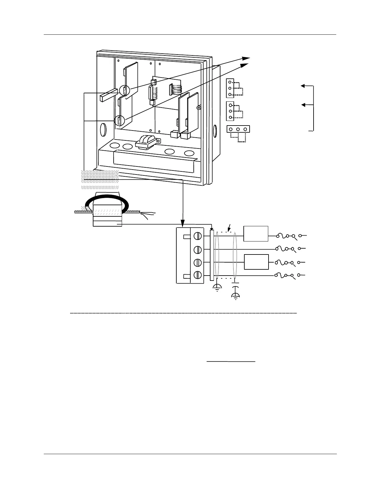
Position when shipped
N.O. with power applied
and OUT indicator light off.
Control
output
#1
PCB
Control
output
#2
PCB
Relay No. 1
W2 = N.O. contact
W3 = N.C. contact
Relay No. 2
W4 = N.O. contact
W5 = N.C. contact
Control output
#1-2 PCB
W5
W4
W3
W2
W6
W7
.
controlled device
than 5 amps
Notes:
1.
2.
3.
J5 terminals 2 and 4 are the non-switched connections to an SPST relay.
Selectable for normally open or normally closed as required.
This relay supplies a dry contact closure. User must supply appropriate
power connections for his external device.
This relay has a resistive load rating of 5A @ 120 Vac
Load calculation example:
Supply voltage
(for example: 115 Vac)
Resistance of customer
=
must equal a
number less
N
H
Plug J5 (see Notes)
Relay 2
load
H
N
Relay 1
load
External Load
power supply
*Relay 2 is used for time proportional duplex.
Also used for 3 position step. See Figure 2-17.
Heat
Cooling
*
Fair-Rite P/N 0443164151
or equivalent
Ferrite Filter
Cable Shield
.0047
Capacitor
F
µ
Capacitor Kit 51197755-001
Install capacitors as shown in figure.
Required for CE Mark Conformity
Kit Part No. 51197612-502, contains two
ferrite filters; Part No.51197612-508
contains 8 ferrite filters. Install inside of
case. See Figure 2-11.
W7 = Relay or
Current Output