Output Calibration - Position Proportional Output Calibration
198 DR4500A Classic Series Circular Chart Recorder With or Without Control Product Manual Release M
April 2017
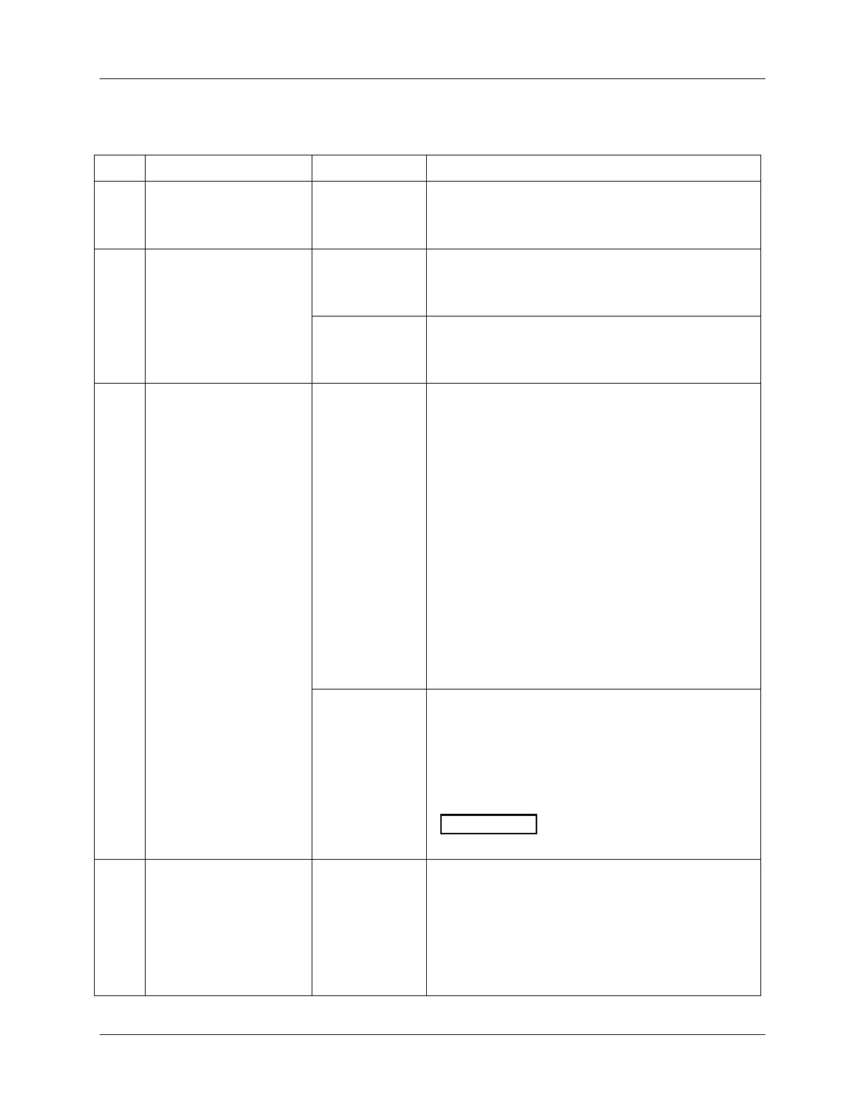
Table 8-3 Position proportional output calibration procedure
Upper Display: CALIB
Lower Display: POS PROP
NOTE: This is the time it
takes the motor to travel
from 0 to 100 %.
Upper Display: (a value)
Lower Display: MTR TIME
Until the proper motor stroke time is reached (see the
motor specs or measure the time).
Range of setting = 5 to 255 Seconds
Select Automatic or
Manual Calibration
Upper Display: DISABL
Lower Display: POS PROP
You can calibrate the control output manually or let
the recorder calibrate the control output
automatically.
In the “Automatic Calibration Mode” (DO AUTO), the
control relays automatically move the motor in the
proper direction.
If desired, however, the motor may be manually
positioned to 0 % and 100 % positions.
Disconnect the relay wires. “DO MAN”.
In the “Manual Calibration Mode” (DO MAN) the
motor does not move. Instead, the existing 0 % and
100 % values may be changed with the ▲ or ▼
keys.
Select automatic or manual calibration.
Upper Display: DO AUTO or DO MAN
Lower Display: POS PROP
If you select DO AUTO, go to step 4.
If you select DO MAN, go to step 6.
When calibration is terminated, this
selection reverts to DISABL.
The decrement relay is turned on to move the motor to
0 % position.
Upper Display: (counts of feedback slidewire)
(0 to 2047)
Lower Display: ZERO VAL
When the motor stops, the display should stop
counting; go to the next step.