Input Calibration - Calibration Set Up and Wiring for PV Inputs
Release M DR4500A Classic Series Circular Chart Recorder With or Without Control Product Manual 185
April 2017
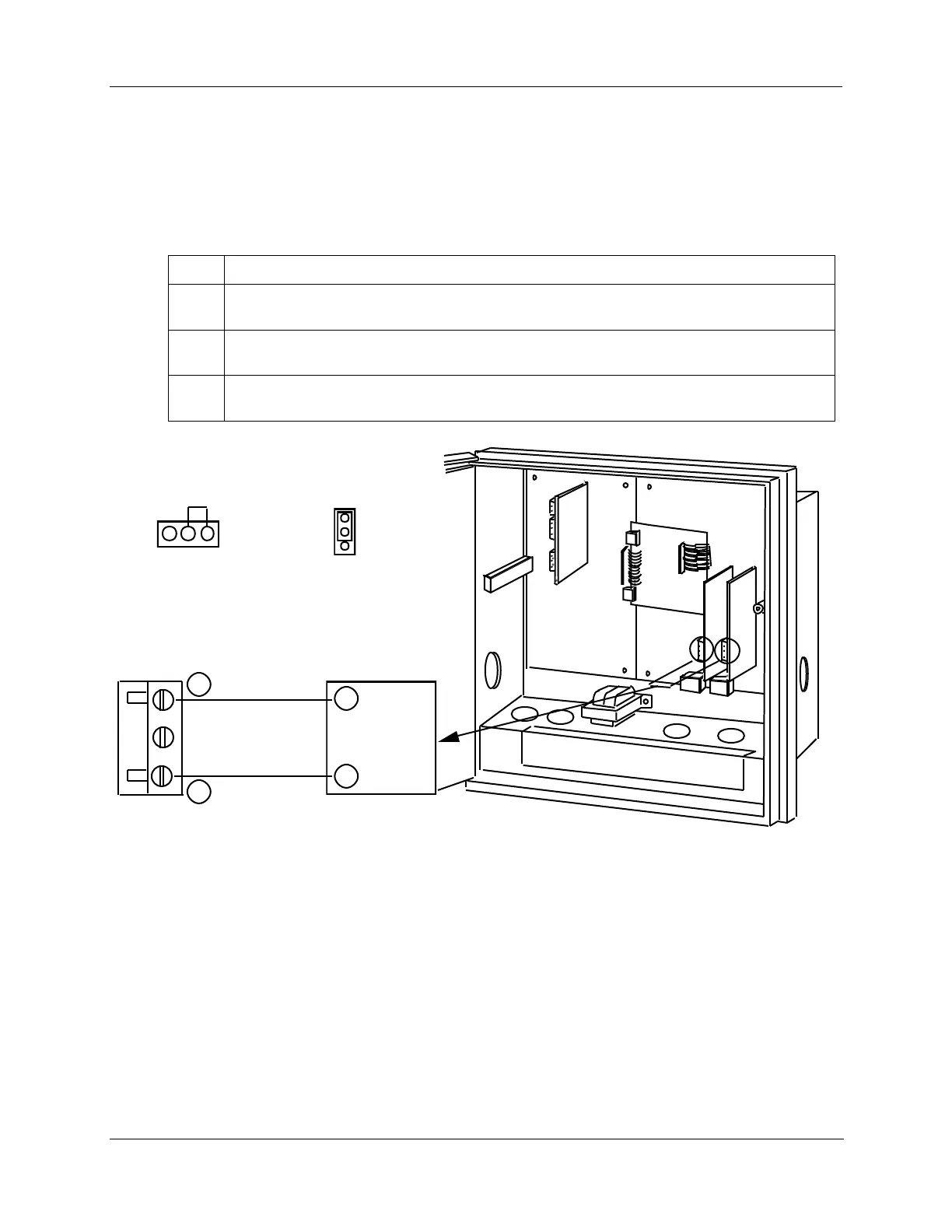
Thermocouple inputs using a compensated calibrator method
Refer to Figure 7-4 and wire the recorder according to the procedure given in Table 7-7.
Table 7-7 Set up wiring procedure for Thermocouple inputs using a compensated
calibrator method
Connect the thermocouple extension wire to the Precision Compensated Calibrator (see
Figure 7-4).
Connect the other end of the thermocouple extension wires to the clamp type terminals in the
plug for the applicable input connector (J2).
Reinstall the plug into the input connector (J2) on the applicable circuit board for Input 1 or
Input 2.
#2 #1
22090
Connector plug J2 f or
inputs #1 or #2
+
_
Thermocouple
extension wires
_
+
Compensated
Calibrator
MA
W1
Be sure W1/MA
jumper is in position
W1 on the input board.
T/C
RTD
Be sure W3 jumper
is in position T/C
on the input board.
Figure 7-4 Calibration set up diagram for Thermocouple inputs using a compensated
calibrator method