Output Calibration - Auxiliary Output Calibration
Release M DR4500A Classic Series Circular Chart Recorder With or Without Control Product Manual 201
April 2017
The procedure for calibrating the Auxiliary Output is listed in Table 8-5. Make sure “LOCKOUT” in the
Set Up group is set to “NONE.” See Section 3 – Configuration. Also, “AUX OUT” must NOT be disabled.
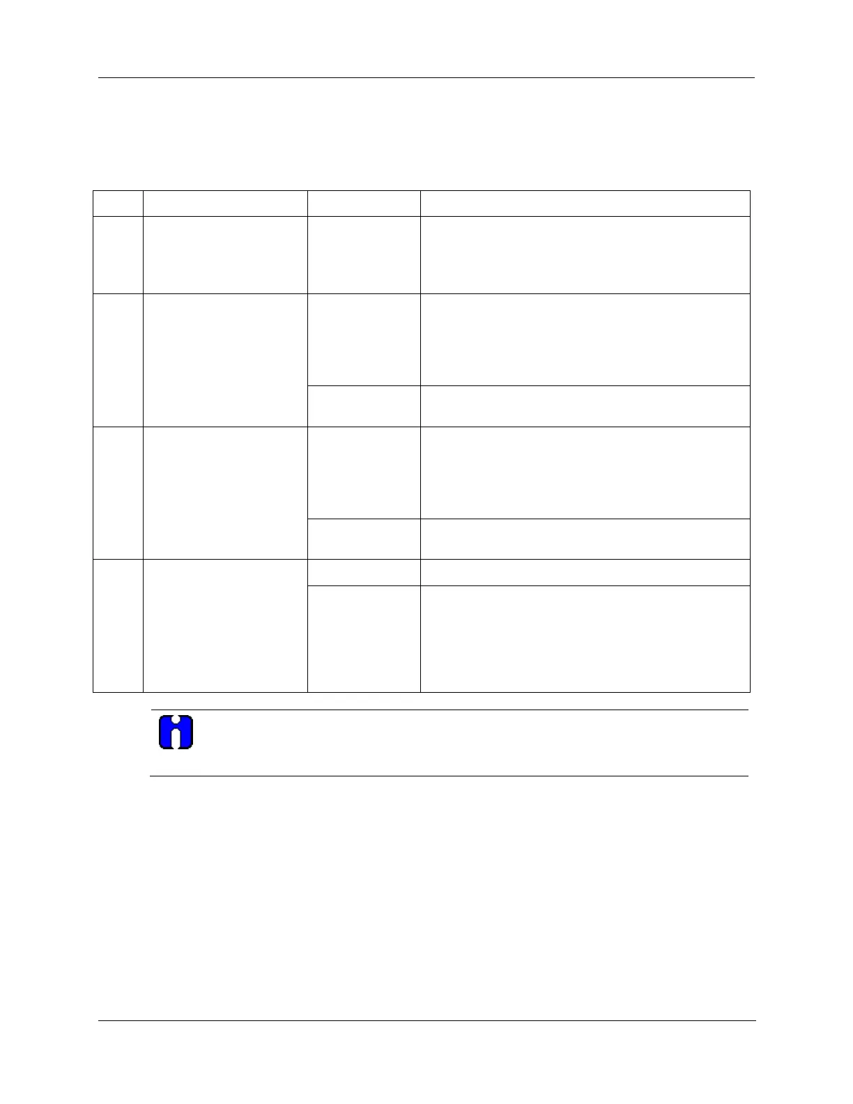
Table 8-5 Auxiliary output calibration procedure
Upper Display: CALIB
Lower Display: AUX OUT
Upper Display: (a value)
(approximately 750)
Lower Display: ZERO VAL
Until the desired 0 % (4 mA) output is read on the
milliammeter.
Stores the 0 % value and you will see:
Upper Display: (a value)
(approximately 3650)
Lower Display: SPAN VAL
Until the desired 100 % (20 mA) output is read on the
milliammeter.
Exit the Calibration Mode
The recorder stores the span value.
To exit the calibration mode.
The calibration for Auxiliary Outputs #2 and #3 follows the procedure for calibrating the current
proportional output (refer to Subsection 8.2).