Troubleshooting / Service
Troubleshooting Procedures
Release M DR4500A Classic Series Circular Chart Recorder With or Without Control Product Manual 217
April 2017
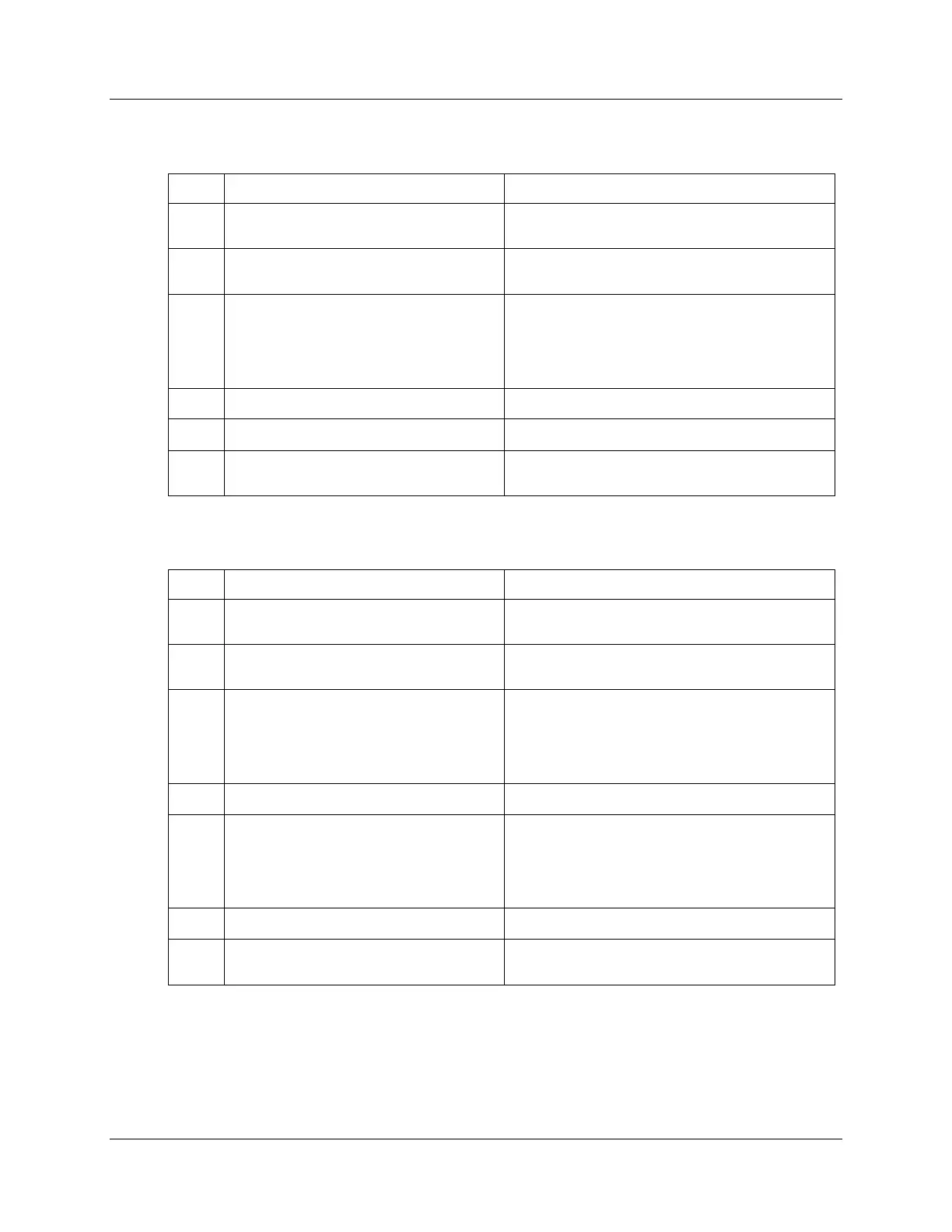
Table 9-14 Procedure #9—Troubleshooting relay output failure symptoms
How to do it or where to find the data
Be sure the recorder is configured for
relay output.
Refer to Section 3 - Configuration. Make sure
OUT ALG selection = TIME.
Be sure all the recorder and control
related data is correct.
Refer to Section 3 - Configuration .
Check the Tuning, Algorithm, and Control data.
Check that the applicable output relay
actuates properly. If it does, go to step 4.
Put the recorder into manual mode and adjust the
output manually to raise or lower the PV around
the setpoint. Listen for the click of the relay as the
PV moves in either direction. Observe OUT 1 or 2
indicator on the front display.
Check the control relay jumper positions.
Refer to Section 3 - Configuration.
Refer to Section 2 - Installation.
Replace the control output printed circuit
board.
Refer to the instructions included with the
replacement part.
Table 9-15 Procedure #10—Troubleshooting current/time or time/current failure
symptoms
How to do it or where to find the data
Be sure the recorder is configured for
current time/time current output.
Refer to Section 3 - Configuration. Make sure
OUT ALG selection = TI CUR or CUR TI.
Be sure all the recorder and control
related data is correct.
Refer to Section 3 - Configuration.
Check the tuning, algorithm, and control data.
Check that the applicable output relay
actuates properly. If it does, go to step 4.
If it does not check the field wiring; then
go to step 5.
Put the recorder into manual mode and adjust the
output manually to raise or lower the PV around
the setpoint. Listen for the click of the relay as the
PV moves in either direction. Observe OUT 1 or 2
indicator on the front display.
Check the control relay jumper positions.
Refer to Section 3 - Configuration.
Check the current proportional output.
Put the recorder in manual mode and manually
adjust the output from 0 to 100% (4–20 mA). Use
a milliammeter across the terminals in connector
J1 on the control output printed circuit board to
verify the output.
Recalibrate the current output.
Refer to Section 8 - Output Calibration.
Replace the control output printed circuit
board.
Refer to the instructions included with the
replacement part.