Parts List
Internal Wiring Diagram – Options Only
Release M DR4500A Classic Series Circular Chart Recorder With or Without Control Product Manual 233
April 2017
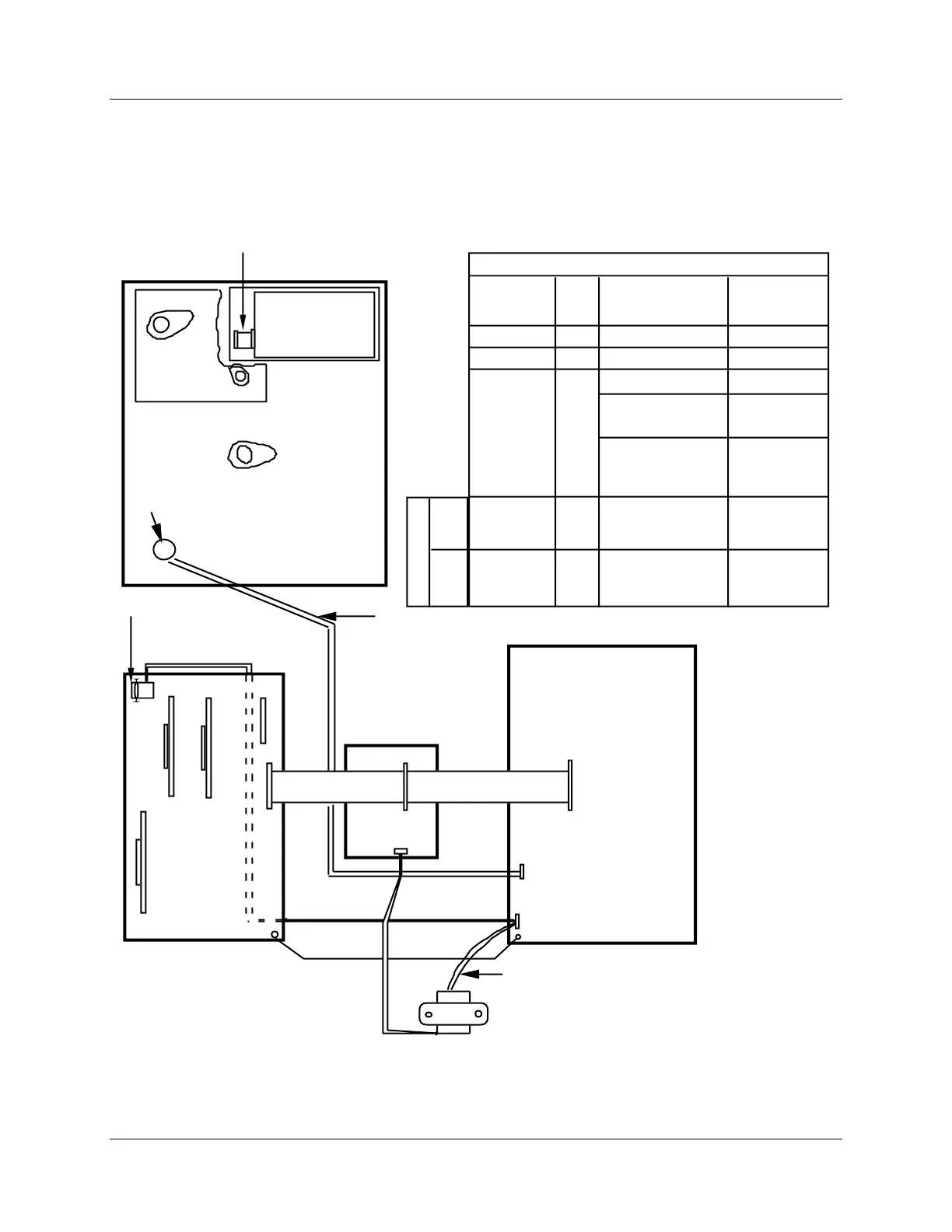
10.5 Internal Wiring Diagram – Options Only
View of internal option wiring
Figure 10-6 is a view of the internal wiring diagram—options only for the DR4500A Classic Recorder.
Chart Plate
Display
board
Pen 2
Motor
Chart motor
9 position keyboard cable
J3
2 wire light
Pen 1 Motor
Alarm/digital
inputs
Mother board
J8
1
J13
J2
Processor
card
J2
J1
1
34 cond.
ribbon cable
Main transf ormer
2 wire
gray pair
J12
Control Output 2
Control Output 1
Auxiliary Output or
Communication
4 cond.
cable
Ground
Test
1
T1
(See Table 1 f or
connections)
Conn.
Designation on
Destinaton Bd.
J4
J4
J4
J2
GRN. WHT.
BLK. RED
2
2
2
4
No.
of
Cond.
Destination
(Board)
BRN.
ORG.
PURPLE
Female Conn.
GRN, WHT,
BLK, RED.
Processor Card
Control Output #1
Control Output #2
Auxiliary Output
Main transf ormerGRN. WHT.
BLK. RED
T1
Leads
TABLE 1
Dual Connector
Male
Conn.
Female
Conn.
22819
Light
option
2 wire pair
No
Connection
Modbus RS485
Communications
J4Auxiliary Output/
Modbus RS485
Communications
Figure 10-6 Internal diagram for DR4500A Classic recorder – options only