Installation - Option Wiring Procedures
Release M DR4500A Classic Series Circular Chart Recorder With or Without Control Product Manual 49
April 2017
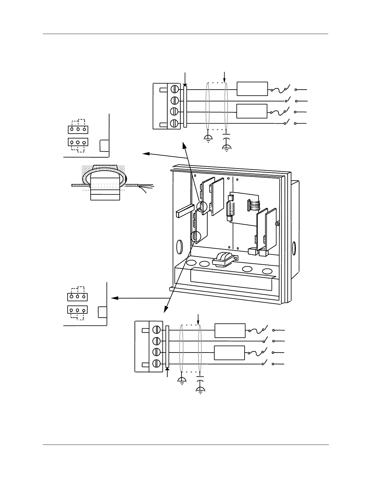
Wiring for alarm outputs #3, 4, 5, and 6
Plug J5
4 - 20 mA
control output
and no. 3 & 4
alarm outputs
PCB
Alarm No. 4
W4 = N.O. contact
W5 = N.C. contact
W3 W2
W5 W4
Alarm No. 3
W2 = N.O. contact
W3 = N.C. contact
#2 #1
21466C
No. 5 & 6
Alarm outputs PCB
W3 W2
W5 W4
Alarm No. 5
W2 = N.O. contact
W3 = N.C. contact
Alarm No. 6
W4 = N.O. contact
W5 = N.C. contact
Alarm #5
Relay Load
Alarm #6
Relay Load
Fair-Rite P/N 0443164151
or equivalent
Ferrite Filter
Ferrite filter
Plug J5
Alarm #3
Relay Load
Alarm #4
Relay Load
External Load
Power Supply
Ferrite filter
External Load
Power Supply
.0047 μF
Cable Shield
Capacitor
.0047 μF
Cable Shield
Capacitor
Capacitor Kit 51197755-001
Install capacitors as shown in figure.
Required for CE Mark Conformity
Kit Part No. 51197612-502, contains two
ferrite filters; Part No.51197612-508
contains 8 ferrite filters. Install inside of
case. See Figure 2-11.
Figure 2-20 Alarm outputs #3, 4, 5, and 6 wiring