#2 #1
22082
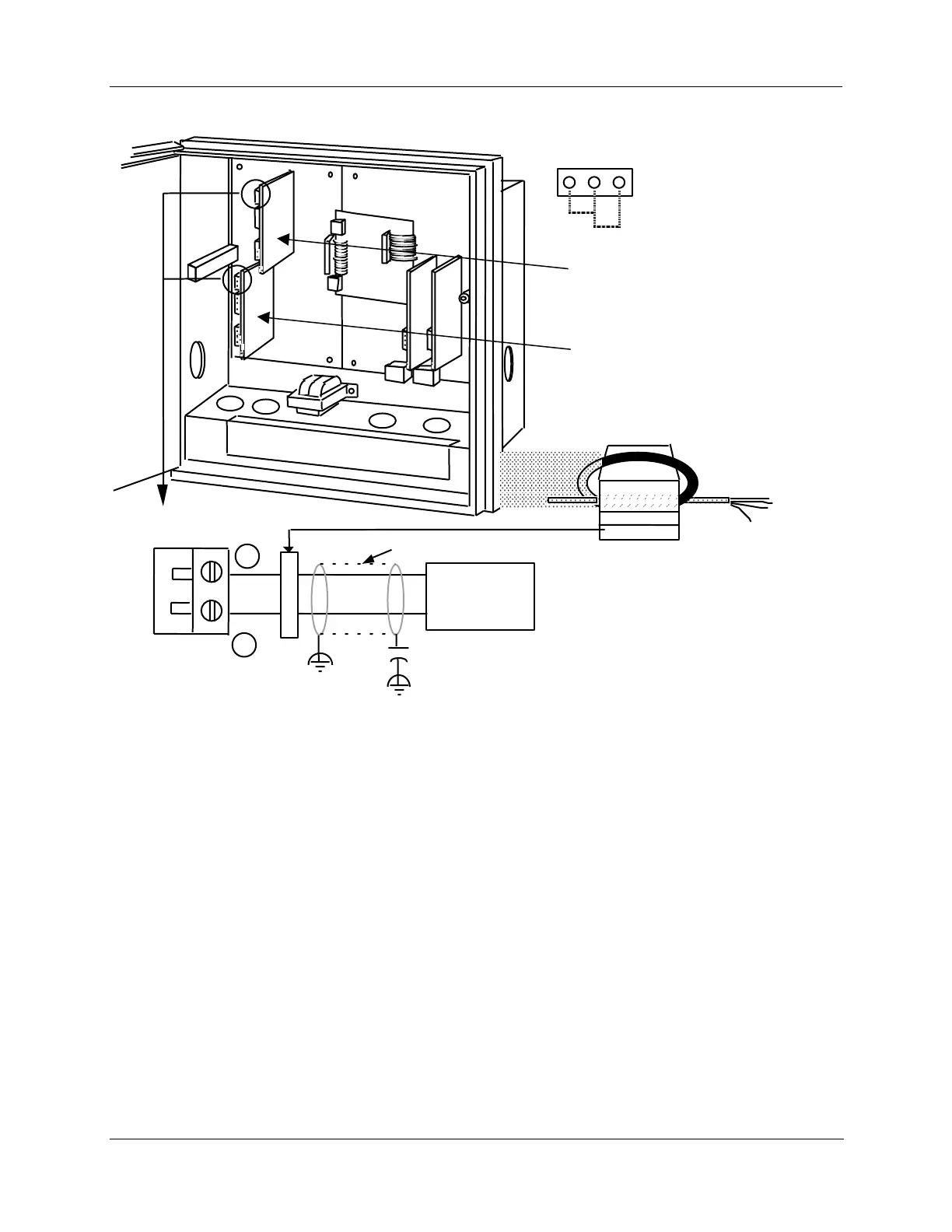
W6
W7
Control Output #1-2 PCB
Current Output Select Jumper
W7 = Relay or
Current Output
+
_
Controller load
0-1000 ohms
4-20 mA
output
Plug J1
Fair-Rite P/N 0443164151
or equivalent
Ferrite Filter
Capacitor Kit 51197755-001
Install capacitors as shown in figure.
Required for CE Mark Conformity
Kit Part No. 51197612-502, contains two
ferrite filters; Part No.51197612-508
contains 8 ferrite filters. Install inside of
case. See Figure 2-11.
Cable Shield
.0047 µF
Capacitor
Control Output #1 PCB
or
Auxiliary Output #2
Control Output #2 PCB
or
Auxiliary Output #3