Input Calibration - Preliminary Information
180 DR4500A Classic Series Circular Chart Recorder With or Without Control Product Manual Release M
April 2017
7.4 Preliminary Information
Disconnect the field wiring
Depending on which input (#1 or #2) you are going to calibrate, tag and disconnect any field wiring
connected to the input terminals on the input boards inside the recorder. Reference Figure 7-1 and follow
the procedure in Table 7-3.
Table 7-3 Disconnect the field wiring
Remove the operating power from the recorder.
Open the door on the recorder.
Loosen the slotted cap screw on the right side of the chart plate, and open the chart plate.
Depending on the input (1 or 2) you are going to calibrate, remove the wired plug from the
input connector (J2) on the applicable circuit board. See Figure 7-1 for the location of the
circuit boards and input connectors.
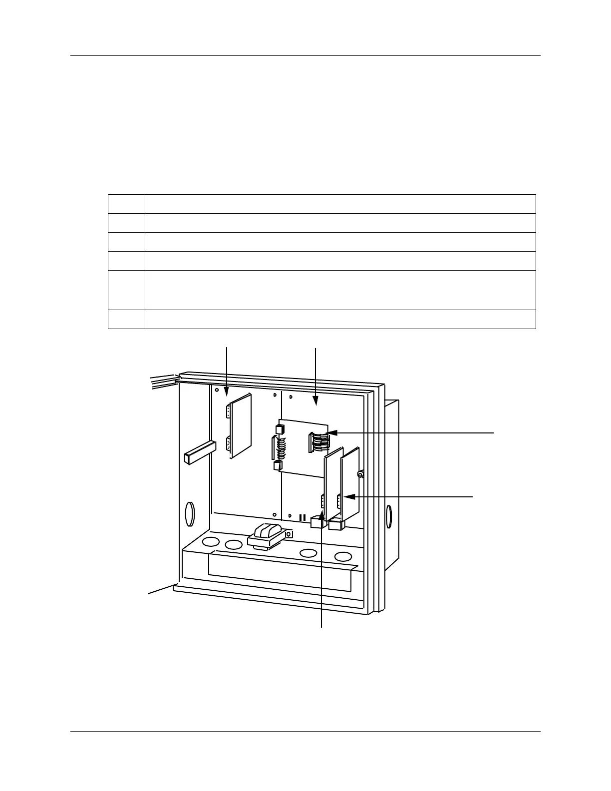
Tag and disconnect the field wiring installed in the applicable input connector plug.
#2 #1
Mother board
for options
22088
Main board
Alarm output
digital input
board (optional)
J2 on input
#1 board
J2 on input #2 board (optional)
Figure 7-1 Location of the input connections on the input boards