Installation - Input Wiring Procedures
Release M DR4500A Classic Series Circular Chart Recorder With or Without Control Product Manual 31
April 2017
circuit-breaker shall be located in close proximity to the recorder, within easy reach of the OPERATOR.
The switch or circuit-breaker shall be marked as the disconnecting device for the recorder.
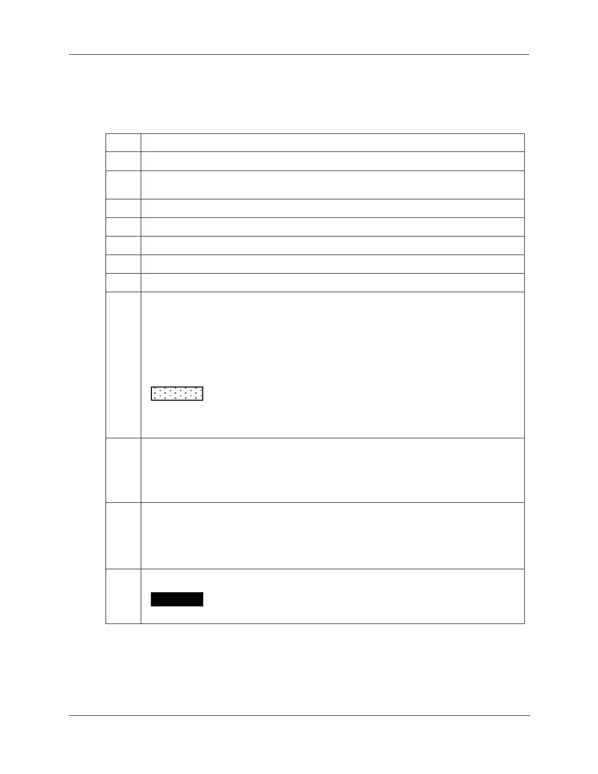
Table 2-11 AC line power wiring
Open the recorder door. Loosen the captive screw in the chart plate and swing the plate out.
Locate connector J10 on the bottom edge of the main printed circuit board. (Refer to Figure
2-12.)
Remove the unwired plug from J10.
Run the power wires separately through second conduit from the right.
For CE Mark conformity, install the ferrite filter as shown in Figure 2-11.
Strip insulation from the end of each wire.
Loosen the screws in plug J10 terminals and position the plug as you would to plug it into J10.
the green wire (G) into the first screw clamp from the right,
the white wire (L2) into the second screw clamp from the right, and
the black wire (L1) into the third screw clamp from the right.
Tighten the screws to secure the wires.
To avoid damaging the recorder, be sure that you install the power wires
into the correct screw clamps. Make sure the fuse block is installed properly for the
given supply rating –– 120 or 240 Vac. The fuse is in the 120 Vac location from the
factory.
Make sure the fuse block is installed in the proper location. Refer to Figure 2-12 for fuse block
location.
120 Vac – Fuse block in location F2
240 Vac – Fuse block in location F1
Dress the wires as slack as possible. This keeps the noise signal on these wires from
bypassing built-in suppression. Also, do not bundle any low level signal wires with the power
wires. Refer to Table 2-10 for permissible wire bundling.
Refer to document 51-52-05-01 for additional information concerning noise interference
prevention.
Insert the wired plug into J10.
Input line voltage will be present on the instrument ground plane if safety
ground is not attached; personal injury and product damage could result.