Input Calibration - Calibration Set Up and Wiring for PV Inputs
182 DR4500A Classic Series Circular Chart Recorder With or Without Control Product Manual Release M
April 2017
7.5 Calibration Set Up and Wiring for PV Inputs
Jumper positions
Before starting the calibration activity, check that the jumper plugs on the applicable input circuit board are
installed in the proper jumper position (in W1/MA and W3) for the particular sensor being used (refer to
the wiring connection drawings in this section for each individual setting).
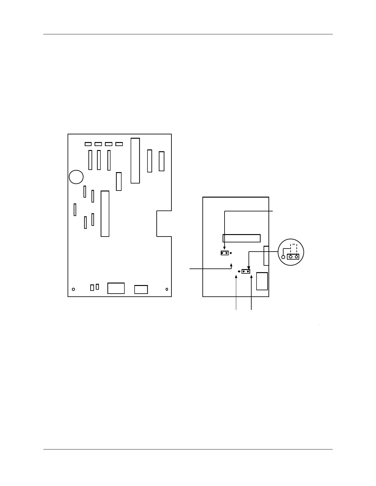
Refer to Figure 7-2 for the location of jumper positions W1/MA and W3 on these circuit boards, and the
status of these jumpers for each type of input sensor.
Main board
Input board
W1
MA
MA
Position MA Position W1
Status of jumper plugs
1. Install W1/MA plug in position W1 f or thermocouple, RTD, Radiamatic, mV, 0-5 Vdc, 0-10 Vdc inputs.
2. Install W1/MA plug in position MA for 4-20 mA inputs.
21443
RTD
W3
Position
T/C
MA
Linear
Position
RTD
3. Install plug in W3 according to y our input type.
T/C
Figure 7-2 Location of jumper positions W1/MA and W3 on the input boards