Installation - Model Number Interpretation
Release M DR4500A Classic Series Circular Chart Recorder With or Without Control Product Manual 15
April 2017
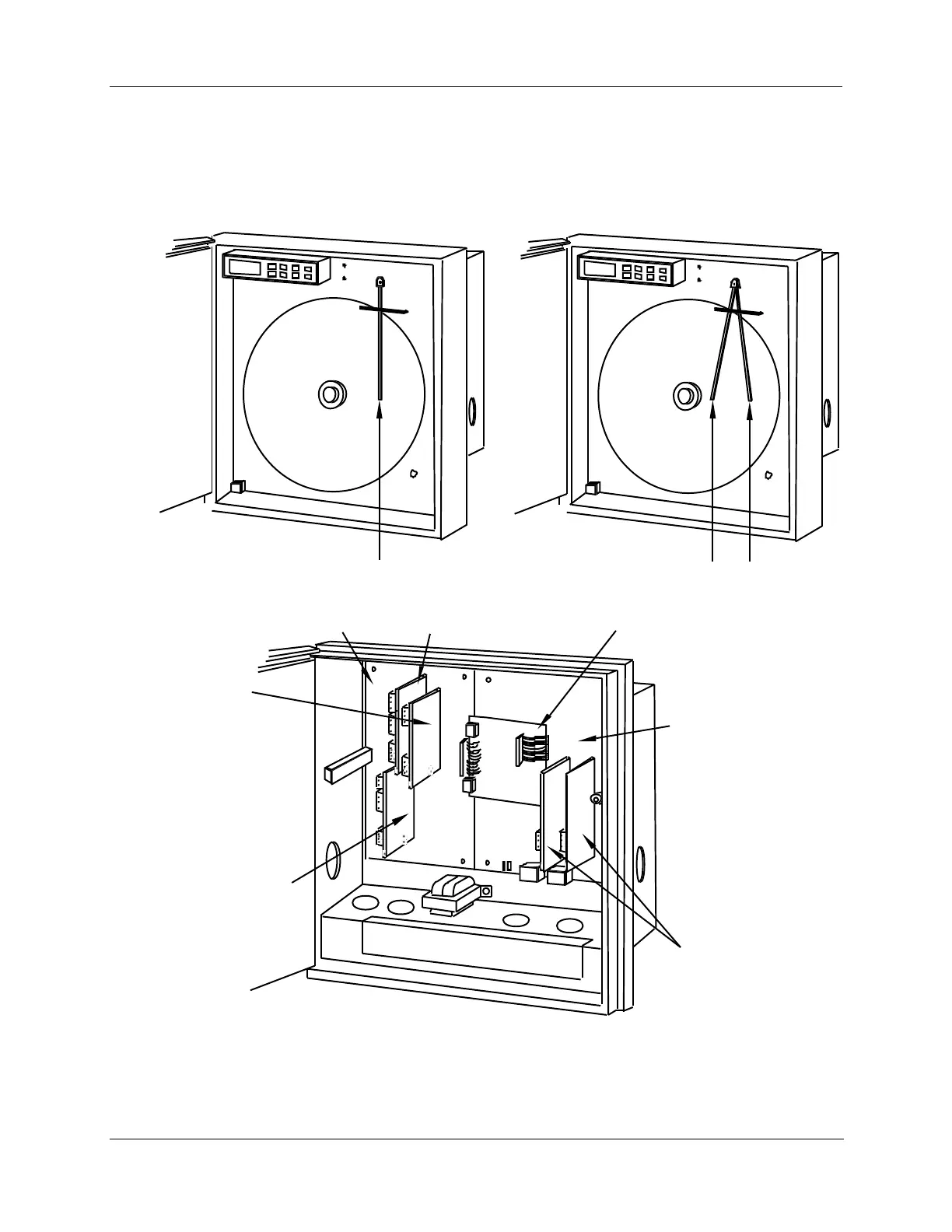
View of hardware components
Figure 2-2 shows the location of the actual hardware components for key number DR45A1 or DR45A2.
Key Number: DR45A1
Main processor
board (common)
#2 #1
Input PCB's
*Table I - XX00
X = 0,1, or 3
Alarm output/digital input PCB
*Table III - XX1
Control output #1 PCB
*Table II - 1X, 6X
Mother PCB (f or control and
selected options)
22077
* Refer to Model Selection Guide
Key Number: DR45A2*
Pen 1
Pen 1Pen 2
Auxiliary Output PCB
*Table III – 1XX
or
Modbus RS485
Communications PCB
•Table III – 3XX
or
Modbus RS485
Communications/Auxiliary
Output PCB
*Table III – 4XX
Control Output #2 PCB
•Table II – X1, X6
Figure 2-2 DR4500A recorder hardware components versus “table” selections