Installation - Lockout Switch Configuration
54 DR4500A Classic Series Circular Chart Recorder With or Without Control Product Manual Release M
April 2017
2.9 Lockout Switch Configuration
Introduction
The configuration can be locked using S1 switch located next to the microprocessor U17 on the main
printed circuit board.
Restrictions based on lockout switch position
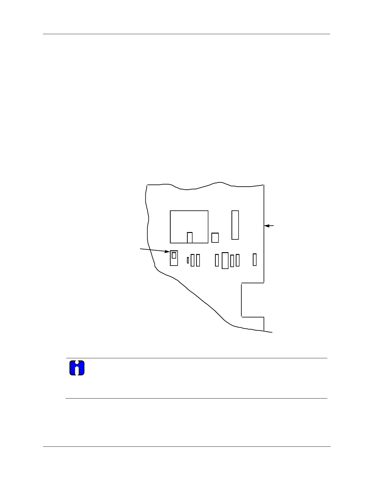
Figure 2-23 shows the location of the S1 lockout switch on the main printed circuit board.
When the lockout switch is OFF (Down—Configure):
You can view and change all applicable operating parameters as described in Section 4 –
Configuration Parameter Definitions.
When the lockout switch is ON (Up—Locked):
Most parameters for the recorder are locked and the parameters may not be changed except for
Tuning 1 and Tuning 2 parameters.
U17
S1
U19
J17
R47
C55
C56
Y2
R45
R43
R42
C50
UP (ON) Locked
DOWN (OFF) Configure
Main Printed
Wiring Board
(Right Side)
S1 Lockout Switch
22709
Figure 2-23 S1 lockout switch location
Lockout can also be configured under set up group “LOCKOUT”. See Subsection 3.18.
This feature also includes the special screw and plate that provide the lead seal capability for
sealing the chart plate.