Release M DR4500A Classic Series Circular Chart Recorder With or Without Control Product Manual
April 2017
2. Installation
2.1 Overview
Introduction
Installation of the DR4500A Recorder consists of mounting and wiring the recorder according to the
instructions given in this section.
Read the preinstallation information, check the model number interpretation and become familiar with your
model selections, then proceed with installation.
What’s in this section?
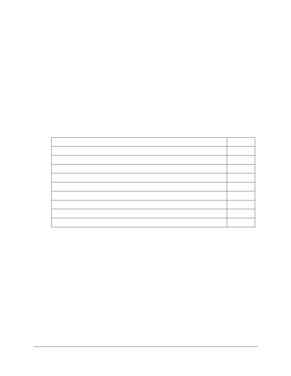
This section contains the following information:
2.2 Model Number Interpretation
2.3 Mounting Considerations and Overall Dimensions
2.6 Input Wiring Procedures
2.7 Output Wiring Procedures
2.8 Option Wiring Procedures
2.9 Lockout Switch Configuration
Pre-installation information
If the recorder has not been removed from its shipping carton, inspect the carton for damage and remove
the recorder. Inspect the unit for any obvious shipping damage and report any damage due to transit to the
carrier.
Make sure a bag containing mounting hardware is included in the carton with the recorder.
Check that the model number shown on the chart plate agrees with what you have ordered.
CE Conformity special conditions (Europe)
Shielded twisted pair cables are required for all Analog I/O, Process Variable, RTD, Thermocouple, dc
millivolt, low level signal, 4-20 mA, and relay output circuits. Supplementary bonding of the recorder
enclosure to a local ground, using 3/4” braided copper conductor, is required. Ferrite suppression filters
(see Subsection 2.5 for Wiring Prerequisites) shall be installed on all cables connected to the
recorder/controller. The cable shield drain wire at the cable load end requires connection through a
0.0047μf capacitor to ground.
Refer to document 51-52-05-01, How to Apply Digital Instrumentation in Severe Electrical Noise
Environments, for additional installation guidance.