22074
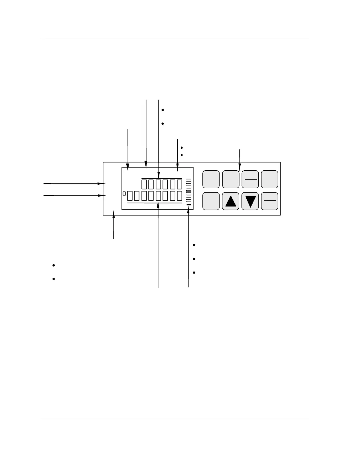
Control relay
1 or 2 is ON,
when lit.
ALM
CHN
RSP
OUT
12 FC
%
RUN
HOLD
MAN
12
Lower Display - eight characters
Normal operation - Displays selectable
operating parameters and values.
Configuration mode - Displays function
group and parameters.
Remote setpoint or
2nd setpoint is
active, when lit.
Blinks when 2nd
setpoint or remote
setpoint is
obtained through
remote switch.
PV displayed is
for channel 1 or 2
Alarm condition
exists for alarm 1
or 2, when lit.
Indicates temperature
units of PV
Upper Display - six characters
Normal operation - Displays process
variable (PV) for selected channel.
Configuration mode - Displays selection or
parameter value.
Indicates controller mode:
MAN = Manual
A = Automatic
Bargraph - deviation (±10% of span)
Center green bar indicates PV is within
±1% of control setpoint.
Next small bar will light if PV is between
±1% but less than ±2% in deviation.
If PV is equal to or greater than ±10%
deviation, the green bar plus all ten small
green bars will light.
12
Key Pad/Key Functions
FUNC
LOWR
DISP
MAN
AUTO
CHART
SET
UP