ELSTER RABO
®
Rotary Gas Meter 10 Honeywell
RABO
®
Rotary Gas Meter 09 Elster Instromet
3. Pull off the index cover.
• It helps to rock it slightly.
• Be careful not to damage the masking plate and
index when removing the cover.
4. Carefully pull off the index masking plate [Figure 12].
Figure 10. Index
Figure 11. Index cover seals
Figure 12. Index masking plate
c) How to “Clock” a Meter
The odometer index can be used to calculate the instantaneous
flow rate by using the right-most digit (test dial). Each number
on this dial represents one (1) cubic foot, and one complete
revolution of this dial represents ten (10) cubic feet. You will
need a stop watch or a watch with a sweep second hand to
calculate flow rate.
1. Measure the time, in seconds, that it takes the test dial to
make one complete revolution (10 cubic feet).
2. Use the following formula to calculate flow rate:
Flow Rate (acfh) = (10 ÷ “time”) x 3600
Note that the odometer index does not compensate for
elevated pressure or temperature. Correction factors will
need to be applied to adjust the ow rate to standard
conditions (scfh)
.
d) Removal, Installation and Replacement
Steps to replace the RABO meter index:
1. Cut the seal wires and remove from the holes [Figure 11].
2. Remove (unscrew) the two brass screws on the sides of
the index cover [Figure 11].
5. Remove the three index retaining screws using a Torx
T20 driver [Figure 13].
Figure 13. Index retaining screws
INDEX
RETAINING
SCREW
INDEX
RETAINING
SCREW
INDEX
RETAINING
SCREW
SEALS
6. Carefully remove the index.
• Pay attention to the driven magnet — it is supported
by the index.
• Leave the magnet on the meter.
7. Transfer the change gear from the damaged index to the
replacement [Figures 14 and 15].
• Remove the change gear on the damaged index.
• Pry the locking collar off with a knife blade or other
sharp object.
• Unscrew the change gear.
!
WARNING
Each meter size uses a common index that has
unique colored gears. Interchanging colored
gears will result in inaccurate readings. Ensure
the replacement index has the same color gears.
[Refer to Table 1]
• If the replacement index has a change gear, remove
and discard it.
• Attach the change gear from the damaged index to
the same shaft on the replacement index.
• Secure gear on shaft.
• Snap on the locking collar.
SUPPORT
HOLE
Figure 5. Horizontal installation
Figure 6. Vertical installation
Figure 7. Sight glass
Figure 4. Side view
b) Mounting
1) Always follow your company’s procedures, and
applicable local codes and ordinances.
2) Ensure gas valves are closed.
3) Ensure the upstream piping is clean and free of any
debris.
4) Remove protective caps from meter inlet and outlet prior
to installation.
5) Ensure the impellers turn freely.
6) Ensure the direction of flow using the arrow on the
nameplate.
7) Ensure the meter orientation is correct. Impeller shafts
must be horizontal [Figure 4].
8) Connect the inlet and outlet pipe flanges using
appropriate bolts and gaskets. Inlet and outlet pipe
flanges should be parallel and should not introduce any
bind on the meter body when tightened.
9) Level meter to within 1/16" per foot in all directions and
tighten flange bolts evenly (maximum 80ft-lbs).
c) Adding Oil
!
WARNING
Add oil only to the index end of the meter.
1) Ensure gas valves are closed and meter and piping are
depressurized.
!
WARNING
Failure to depressurize the meter prior to removing
meter and/or components could result in personal
injury and/or property damage.
2) Remove oil fill plug in the counter end case cover using a
5mm hex key [Figures 5 and 6].
3) Using the supplied syringe and oil, slowly add oil until
it is +/-1/16" of the center of the sight glass [Figure 7].
DO NOT OVERFILL. Only use Shell Morlina lubricating oil.
!
WARNING
DO NOT remove any sight glasses. No maintenance
can be performed through these openings.
4) Reinstall the oil fill plug.
OIL
FILL
OIL
LEVEL
SIGHT
GLASS
OIL
DRAIN
OIL
FILL
OIL
FILL
OIL
FILL
OIL
LEVEL
SIGHT
GLASS
OIL
DRAIN
RABO
®
Rotary Gas Meter 04 Elster Instromet
c) How to “Clock” a Meter
d) Removal, Installation and Replacement
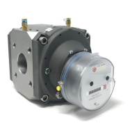
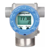
Figure 10. Index
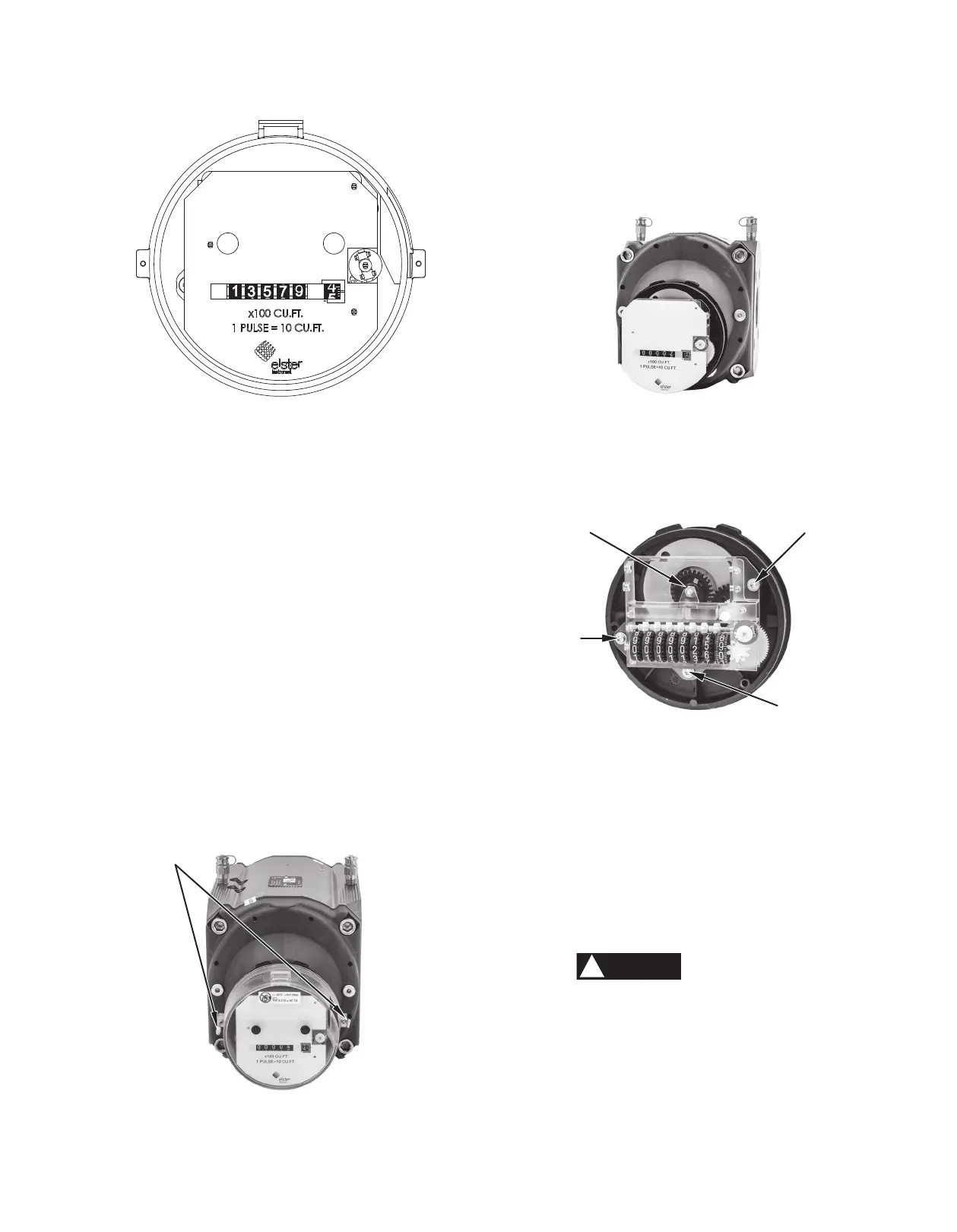
Figure 11. Index cover seals
Figure 12. Index masking plate
Figure 13. Index retaining screws
The odometer index can be used to calculate the instantaneous
flow rate by using the right-most digit (test dial). Each number
on this dial represents one (1) cubic foot, and one complete
revolution of this dial represents ten (10) cubic feet. You will
need a stop watch or a watch with a sweep second hand to
calculate flow rate.
1. Measure the time, in seconds, that it takes the test dial to
make one complete revolution (10 cubic feet).
2. Use the following formula to calculate flow rate:
Flow Rate (acfh) = (10 ÷ “time”) x 3600
Note that the odometer index does not compensate for
elevated pressure or temperature. Correction factors will
need to be applied to adjust the flow rate to standard
conditions (scfh).
Steps to replace the RABO meter index:
1. Cut the seal wires and remove from the holes [Figure 11].
2. Remove (unscrew) the two brass screws on the sides of
the index cover [Figure 11].
3. Pull off the index cover.
• It helps to rock it slightly.
• Be careful not to damage the masking plate and
index when removing the cover.
4. Carefully pull off the index masking plate [Figure 12].
5. Remove the three index retaining screws using a Torx
T20 driver [Figure 13].
6. Carefully remove the index.
• Pay attention to the driven magnet — it is supported
by the index.
• Leave the magnet on the meter.
7. Transfer the change gear from the damaged index to the
replacement [Figures 14 and 15].
• Remove the change gear on the damaged index.
• Pry the locking collar off with a knife blade or other
sharp object.
• Unscrew the change gear.
• If the replacement index has a change gear, remove
and discard it.
• Attach the change gear from the damaged index to
the same shaft on the replacement index.
• Secure gear on shaft.
• Snap on the locking collar.
Each meter size uses a common index that has
unique colored gears. Interchanging colored
gears will result in inaccurate readings. Ensure
the replacement index has the same color gears.
[Refer to Table 1]

 Loading...