ELSTER RABO
®
Rotary Gas Meter 11 Honeywell
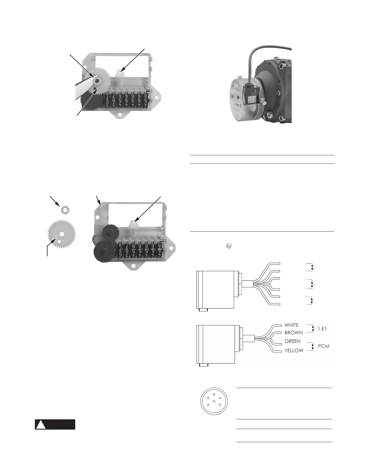
Pulser Pin-Out Connections
Connector
1.E1
Pulse
Out 1
2.E1
Pulse
Out 2
PCM
Tamper
Circuit
IN-S11 1 + 2 5 + 6 3 + 4
IN-S12
1 + 2
(Back)
1 + 2
(Front)
3 + 4
(Front)
WHITE
BROWN
GREEN
YELLOW
GREY
PINK
1.E1
2.E1
PCM
Figure 17. Pulser connections
Technical Specifications
Description Min. Typ. Max. Unit
Voltage (U) 24
V
Current (I) 76 mA
Power (P) 1.1
W
Static Contact Resistance 200 mΩ
Insulation Resistance 10
9
Ω
Breakdown Voltage 100 100 VDC
Switching Time Including Bounce 0.5 ms
Release Time 0.1 ms
Temperature range: -40°C … +70°C
IP-Class: IP67
Explosion protection:
II 2 G EEx ia 2C T4
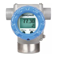
Figure 16. IN-S10 pulser installed
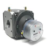
Figure 15. Index, change gear and locking collar
8. Install the replacement index.
• Orient the index so the mounting holes line up with
the posts in the base plate.
• Carefully ensure the shaft on the magnet holder is in
the support hole on the index frame [Figure 13].
• Install the three screws to retain the index to the base
plate. Tighten to snug.
9. Install index masking plate.
10. Install index cover.
11. Install security seals.
LOCKING COLLAR
CHANGE GEAR
INDEX
Meter Gear Color
3.5M/G65 White
5.5M/G100 Dark Green
9M/G160 Green
14M/G250
Red
Table 1
LOCKING COLLAR
CHANGE GEAR
SUPPORT HOLE
SUPPORT HOLE
Figure 14. Change gear removal
12. Pulser
All RABO meter indexes can be easily outfitted with a pulse output
device to interface with auxiliary equipment. Installation of a pulser
is quick and easy, and requires no disassembly. To install a pulser,
simply slide the pulser into the slot on the index cover [Figure 16],
and connect the wires to the desired auxiliary devices [Figure 17].
The pulser can be secured to the index cover screw with a seal wire
to mitigate and indicate tampering.
!
WARNING
Explosion Hazard
Auxiliary equipment and interconnecting wiring must be in
accordance with local and national codes for hazardous areas.
1
2
3
4
5 6
RABO
®
Rotary Gas Meter 10 Elster Instromet
Pulser Pin-Out Connections
Connector
1.E1
Pulse
Out 1
2.E1
Pulse
Out 2
PCM
Tamper
Circuit
IN-S11 1 + 2 5 + 6 3 + 4
IN-S12
1 + 2
(Back)
1 + 2
(Front)
3 + 4
(Front)
WHITE
BROWN
GREEN
YELLOW
GREY
PINK
1.E1
2.E1
PCM
Figure 17. Pulser connections
Technical Specifications
Description Min. Typ. Max. Unit
Voltage (U) 24
V
Current (I) 76 mA
Power (P) 1.1
W
Static Contact Resistance 200 mΩ
Insulation Resistance 10
9
Ω
Breakdown Voltage 100 100 VDC
Switching Time Including Bounce 0.5 ms
Release Time 0.1 ms
Temperature range: -40°C … +70°C
IP-Class: IP67
Explosion protection:
II 2 G EEx ia 2C T4
Figure 16. IN-S10 pulser installed
Figure 15. Index, change gear and locking collar
8. Install the replacement index.
• Orient the index so the mounting holes line up with
the posts in the base plate.
• Carefully ensure the shaft on the magnet holder is in
the support hole on the index frame [Figure 13].
• Install the three screws to retain the index to the base
plate. Tighten to snug.
9. Install index masking plate.
10. Install index cover.
11. Install security seals.
LOCKING COLLAR
CHANGE GEAR
INDEX
Meter Gear Color
3.5M/G65 White
5.5M/G100 Dark Green
9M/G160 Green
14M/G250
Red
Table 1
LOCKING COLLAR
CHANGE GEAR
SUPPORT HOLE
SUPPORT HOLE
Figure 14. Change gear removal
12. Pulser
All RABO meter indexes can be easily outfitted with a pulse output
device to interface with auxiliary equipment. Installation of a pulser
is quick and easy, and requires no disassembly. To install a pulser,
simply slide the pulser into the slot on the index cover [Figure 16],
and connect the wires to the desired auxiliary devices [Figure 17].
The pulser can be secured to the index cover screw with a seal wire
to mitigate and indicate tampering.
!
WARNING
Explosion Hazard
Auxiliary equipment and interconnecting wiring must be in
accordance with local and national codes for hazardous areas.
1
2
3
4
5 6
RABO
®
Rotary Gas Meter 10 Elster Instromet
Figure 5. Horizontal installation
Figure 6. Vertical installation
Figure 7. Sight glass
Figure 4. Side view
b) Mounting
1) Always follow your company’s procedures, and
applicable local codes and ordinances.
2) Ensure gas valves are closed.
3) Ensure the upstream piping is clean and free of any
debris.
4) Remove protective caps from meter inlet and outlet prior
to installation.
5) Ensure the impellers turn freely.
6) Ensure the direction of flow using the arrow on the
nameplate.
7) Ensure the meter orientation is correct. Impeller shafts
must be horizontal [Figure 4].
8) Connect the inlet and outlet pipe flanges using
appropriate bolts and gaskets. Inlet and outlet pipe
flanges should be parallel and should not introduce any
bind on the meter body when tightened.
9) Level meter to within 1/16" per foot in all directions and
tighten flange bolts evenly (maximum 80ft-lbs).
c) Adding Oil
!
WARNING
Add oil only to the index end of the meter.
1) Ensure gas valves are closed and meter and piping are
depressurized.
!
WARNING
Failure to depressurize the meter prior to removing
meter and/or components could result in personal
injury and/or property damage.
2) Remove oil fill plug in the counter end case cover using a
5mm hex key [Figures 5 and 6].
3) Using the supplied syringe and oil, slowly add oil until
it is +/-1/16" of the center of the sight glass [Figure 7].
DO NOT OVERFILL. Only use Shell Morlina lubricating oil.
!
WARNING
DO NOT remove any sight glasses. No maintenance
can be performed through these openings.
4) Reinstall the oil fill plug.
OIL
FILL
OIL
LEVEL
SIGHT
GLASS
OIL
DRAIN
OIL
FILL
OIL
FILL
OIL
FILL
OIL
LEVEL
SIGHT
GLASS
OIL
DRAIN
RABO
®
Rotary Gas Meter 04 Elster Instromet
Figure 14. Change gear removal
Figure 15. Index, change gear and locking collar
Figure 16. IN-S10 pulser installed
Figure 17. Pulser connections
Table 1
Meter Gear Color
3.5M/G65
5.5M/G100
9M/G160
14M/G250
White
Dark Green
Green
Red
12. Pulser
8. Install the replacement index.
• Orient the index so the mounting holes line up with
the posts in the base plate.
• Carefully ensure the shaft on the magnet holder is in
the support hole on the index frame [Figure 13].
• Install the three screws to retain the index to the base
plate. Tighten to snug.
9. Install index masking plate.
10. Install index cover.
11. Install security seals.
All RABO meter indexes can be easily outfitted with a pulse output
device to interface with auxiliary equipment. Installation of a
pulser is quick and easy, and requires no disassembly. To install
a pulser, simply slide the pulser into the slot on the index cover
[Figure 16], and connect the wires to the desired auxiliary devices
[Figure 17]. The pulser can be secured to the index cover screw with
a seal wire to mitigate and indicate tampering.
Explosion Hazard
Auxiliary equipment and interconnecting wiring must be in
accordance with local and national codes for hazardous areas.
Pulser Pin-Out Connections
Connector
1.E1
Pulse
Out 1
2.E1
Pulse
Out 2
PCM
Tamper
Circuit
IN-S11 1 + 2 5 + 6 3 + 4
IN-S12
1 + 2
(Back)
1 + 2
(Front)
3 + 4
(Front)
WHITE
BROWN
GREEN
YELLOW
GREY
PINK
1.E1
2.E1
PCM
Figure 17. Pulser connections
Technical Specifications
Description Min. Typ. Max. Unit
Voltage (U) 24
V
Current (I) 76 mA
Power (P) 1.1
W
Static Contact Resistance 200 mΩ
Insulation Resistance 10
9
Ω
Breakdown Voltage 100 100 VDC
Switching Time Including Bounce 0.5 ms
Release Time 0.1 ms
Temperature range: -40°C … +70°C
IP-Class: IP67
Explosion protection:
II 2 G EEx ia 2C T4
Figure 16. IN-S10 pulser installed
Figure 15. Index, change gear and locking collar
8. Install the replacement index.
• Orient the index so the mounting holes line up with
the posts in the base plate.
• Carefully ensure the shaft on the magnet holder is in
the support hole on the index frame [Figure 13].
• Install the three screws to retain the index to the base
plate. Tighten to snug.
9. Install index masking plate.
10. Install index cover.
11. Install security seals.
LOCKING COLLAR
CHANGE GEAR
INDEX
Meter Gear Color
3.5M/G65 White
5.5M/G100 Dark Green
9M/G160 Green
14M/G250
Red
Table 1
LOCKING COLLAR
CHANGE GEAR
SUPPORT HOLE
SUPPORT HOLE
Figure 14. Change gear removal
12. Pulser
All RABO meter indexes can be easily outfitted with a pulse output
device to interface with auxiliary equipment. Installation of a pulser
is quick and easy, and requires no disassembly. To install a pulser,
simply slide the pulser into the slot on the index cover [Figure 16],
and connect the wires to the desired auxiliary devices [Figure 17].
The pulser can be secured to the index cover screw with a seal wire
to mitigate and indicate tampering.
!
WARNING
Explosion Hazard
Auxiliary equipment and interconnecting wiring must be in
accordance with local and national codes for hazardous areas.
1
2
3
4
5 6
RABO
®
Rotary Gas Meter 10 Elster Instromet
(Ui)
(Ii)
(Pi)
V
I
25
V
I
0,25
V
I
II 2 G Ex ia IIC T4 Gb
Pulser Pin-Out Connections
Connector
1.E1
Pulse
Out 1
2.E1
Pulse
Out 2
PCM
Tamper
Circuit
IN-S11 1 + 2 5 + 6 3 + 4
IN-S12
1 + 2
(Back)
1 + 2
(Front)
3 + 4
(Front)
WHITE
BROWN
GREEN
YELLOW
GREY
PINK
1.E1
2.E1
PCM
Figure 17. Pulser connections
Technical Specifications
Description Min. Typ. Max. Unit
Voltage (U) 24
V
Current (I) 76 mA
Power (P) 1.1
W
Static Contact Resistance 200 mΩ
Insulation Resistance 10
9
Ω
Breakdown Voltage 100 100 VDC
Switching Time Including Bounce 0.5 ms
Release Time 0.1 ms
Temperature range: -40°C … +70°C
IP-Class: IP67
Explosion protection: II 2 G EEx ia 2C T4
Figure 16. IN-S10 pulser installed
Figure 15. Index, change gear and locking collar
8. Install the replacement index.
• Orient the index so the mounting holes line up with
the posts in the base plate.
• Carefully ensure the shaft on the magnet holder is in
the support hole on the index frame [Figure 13].
• Install the three screws to retain the index to the base
plate. Tighten to snug.
9. Install index masking plate.
10. Install index cover.
11. Install security seals.
LOCKING COLLAR
CHANGE GEAR
INDEX
Meter Gear Color
3.5M/G65 White
5.5M/G100 Dark Green
9M/G160 Green
14M/G250 Red
Table 1
LOCKING COLLAR
CHANGE GEAR
SUPPORT HOLE
SUPPORT HOLE
Figure 14. Change gear removal
12. Pulser
All RABO meter indexes can be easily outfitted with a pulse output
device to interface with auxiliary equipment. Installation of a pulser
is quick and easy, and requires no disassembly. To install a pulser,
simply slide the pulser into the slot on the index cover [Figure 16],
and connect the wires to the desired auxiliary devices [Figure 17].
The pulser can be secured to the index cover screw with a seal wire
to mitigate and indicate tampering.
!
WARNING
Explosion Hazard
Auxiliary equipment and interconnecting wiring must be in
accordance with local and national codes for hazardous areas.
1
2
3
4
5 6
RABO
®
Rotary Gas Meter 10 Elster Instromet

 Loading...