RABO
®
Rotary Gas Meter 11 Elster Instromet
ACCESSORY
Problem Probable Cause Suggested Action
Excessive vibration Build-up of foreign material on impellers Clean by flushing, or replace worn parts
Misalignment Level meter in piping
Worn bearings Replace bearings
Worn timing gears Replace timing gears
Impellers contacting body Rotate manually to verify impellers spin freely
High differential pressure Heavyweight or too much oil Check oil level and condition
Dirt deposits on impellers Remove dirt by flushing
Impellers out of time Retime impellers
Impellers contacting body Rotate manually to verify impellers spin freely
Low registration Upstream or bypass leak Check all valves for leakage
Non-registration Broken or binding index odometer Replace odometer
Obstruction in meter Remove meter, remove obstructions, flush meter
15. Troubleshooting
Figure 19. Horizontal installation
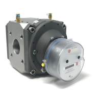
14. Auxiliary Equipment Mounting
All RABO meters are equipped with threaded holes for mounting
compact, lightweight auxiliary equipment [Figures 19 and 20].
All holes are M6 x 1 by 10mm deep. Heavier equipment should
be pipe or wall mounted adjacent to the meter. Elster provides
customized brackets for commonly used equipment [Figure 21].
Please contact your local Elster representative for details.
NPT AUXILIARY PORTS
Figure 18. Auxiliary ports
Figure 20. Vertical installation
13. Thermowell
All RABO meters come equipped with two (2) ¼" NPT auxiliary
ports on the meter body [Figure 18], which can be used for sensing
pressure and temperature of the flowing gas. A thermowell is
required when using a temperature sensing device. Thermowells
are available as accessories to the meter.
a) Installing a Thermowell
1. If meter is not installed in the gas piping, go to Step 5.
2. Slowly open bypass valve.
3. Slowly close the meter’s outlet valve, then the inlet valve.
4. Slowly, completely depressurize the meter piping.
5. Remove one of the plugs in the meter body by using a
¼" hex key.
6. Apply Teflon tape or pipe dope to the male threads of the
thermowell. Wipe excess pipe dope off the thermowell
probe and leading threads to ensure no pipe dope
enters the metering chamber.
7. Screw the thermowell into the meter and tighten to
18 ft-lbs.
8. Re-pressurize the meter as instructed in Start-up/
Commissioning (see section 6).
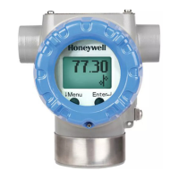
Figure 21. Auxilary equipment mounted
ACCESSORY
Figure 18. Auxiliary ports
13. Thermowell
All RABO meters come equipped with two (2) ¼“ NPT auxiliary
ports on the meter body [Figure 18], which can be used for sensing
pressure and temperature of the flowing gas. A thermowell is
required when using a temperature sensing device. Thermowells
are available as accessories to the meter.
a) Installing a Thermowell
1. If meter is not installed in the gas piping, go to Step 5.
2. Slowly open bypass valve.
3. Slowly close the meter’s outlet valve, then the inlet valve.
4. Slowly, completely depressurize the meter piping.
5. Remove one of the plugs in the meter body by using a
¼“ hex key.
6. Apply Teflon tape or pipe dope to the male threads of the
thermowell. Wipe excess pipe dope off the thermowell
probe and leading threads to ensure no pipe dope
enters the metering chamber.
7. Screw the thermowell into the meter and tighten to
18 ft-lbs.
8. Re-pressurize the meter as instructed in Start-up/
Commissioning (see section 6).
14. Instrument Drive (ID)
RABO meters (3.5M/G65 and 5.5M/G100) can be retrofitted with
an instrument drive, or instrument adaptor plate. The ID provides a
mounting surface for instruments requiring mechanical rotational
input. The drive rate of the RABO ID is 10 cubic feet per 1 revolution
in a clockwise direction. When installing an instrument, orient
the instrument face to the FRONT edge of the adaptor plate. The
threads in the adaptor plate for instrument mounting are 5/16“ - 18.
a) Retrofit a CTR (CTR = Uncorrected Mechanical Totalizer) meter
with an Instrument Drive (ID).
i) Remove index. See section 11. d) 1 to 11. d) 6
ii) Transfer the change gear from the CTR index to the ID
gearing and index assembly [Figure 14 and 20].
(1) Pry the change gear’s locking collar off with
a knife blade or other similar object.
(2) Unscrew the change gear from the CTR index.
(3) Attach the change gear to the middle gear on the back
side of the ID gearing and index assembly.
(4) Reinstall locking collar to retain the change gear.
iii) Remove the magnet holder assembly from the meter
[Figure 21].
Figure 19. RABO with Instrument Drive
Figure 20. Change gear installation on ID gearing and index
assembly
CHANGE
GEAR
LOCKING
COLLAR
Figure 21. Magnet holder
MAGNET
HOLDER
ASSEMBLY

 Loading...