ELSTER RABO
®
Rotary Gas Meter 13 Honeywell
iv) Unscrew the lock nut from the magnet holder
(THREADS ARE LEFT HAND) [Figure 17].
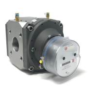
v) Unscrew the change gear from the magnet holder
(THREADS ARE LEFT HAND) [Figure 22].
vi) Assemble the change gear to the ID magnet holder
(THREADS ARE LEFT HAND).
(1) For 3.5M meters
(a) Apply Loctite
®
770 primer to the threads and mating
surfaces of the change gear and the magnet holder
[Figure 23]. Allow to dry for 30 seconds.
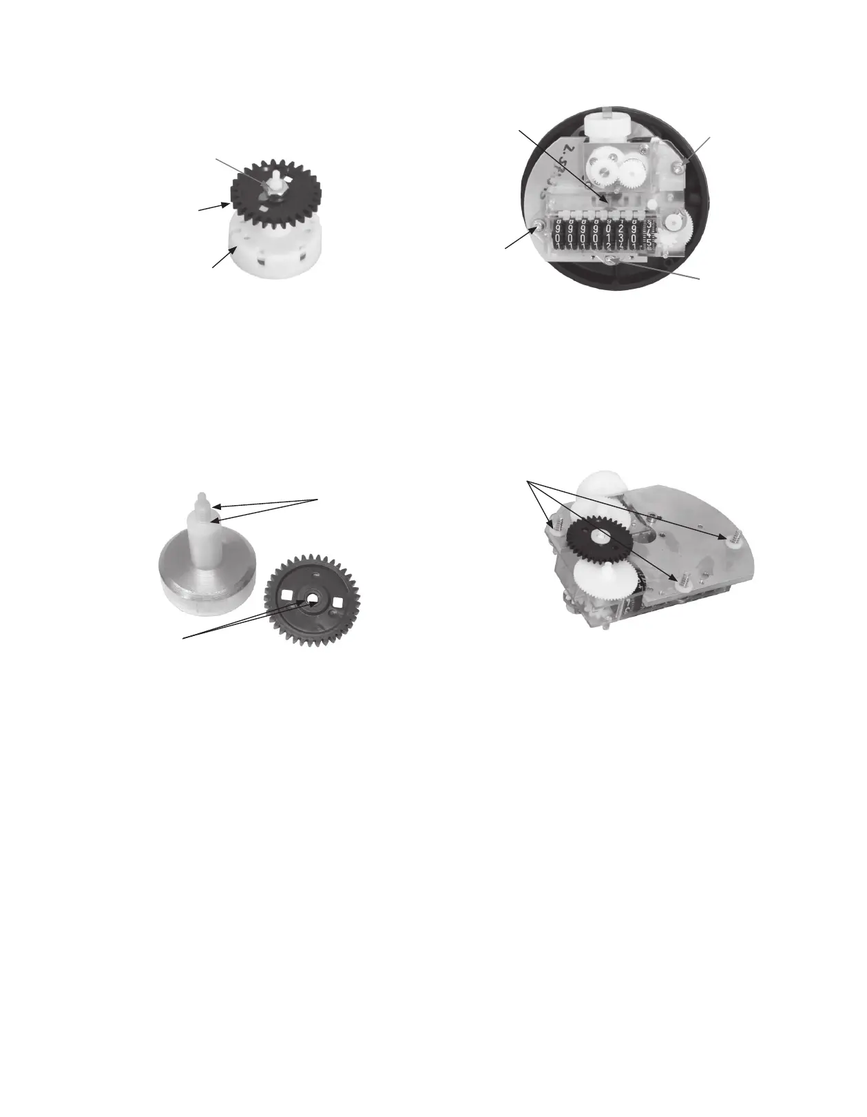
Figure 22. Magnet holder, change gear, and lock nut
CHANGE
GEAR
MAGNET
HOLDER
LOCK
NUT
Figure 23. Magnet holder and change gear adhesive application
for 3.5M meter.
APPLY LOCTITE
®
PRIMER
APPLY LOCTITE
®
PRIMER. APPLY
CA
(b) Apply Loctite
®
406, Loctite
®
495, or equivalent
Cyanoacrylate adhesive to the threads and mating
surface of the magnet holder [Figure 23]. Do not get
the adhesive on the small tip of the magnet holder.
(c) Quickly screw the change gear to the magnet holder
(THREADS ARE LEFT HAND) and tighten until gear
is snugly seated against magnet holder. Let dry
completely
(d) Do not reinstall the locknut for a 3.5M meter.
(2) For 5.5M meters
(a) Screw the change gear to the magnet holder
(THREADS ARE LEFT HAND) and tighten until gear is
snugly seated against magnet holder.
(b) Reinstall the lock nut (THREADS ARE LEFT HAND)
removed in a previous step. Tighten until snug.
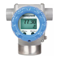
vii) Install the ID magnet holder onto the end of the meter.
viii) Install the ID gearing and index assembly on meter.
(1) Orient the ID gearing and index assembly so the
mounting screws line up with the posts in the index
base plate.
(2) Ensure the shaft on the magnet holder aligns with
the support hole on the index frame [Figure 24].
Figure 24.
ID retaining screws
INDEX
RETAINING
SCREW
SUPPORT
HOLE (ON
BACK SIDE)
INDEX
RETAINING
SCREW
INDEX
RETAINING
SCREW
(3) Tighten the three screws until snug. Do not overtighten.
(a) Each screw should have a 2mm thick retaining
washer to space the ID gearing and index assembly
away from the base plate [Figure 25]. The spacers
are installed at the factory. Verify they have not
fallen off.
Figure 25.
Retaining washers
RETAINING
WASHER
ix) Check for binds
(1) Using compressed air blown into the meter inlet port,
confirm the index and ID output shaft rotate freely.
x) Snap the ID index masking plate onto three posts
of the index.
xi) Install the ID index cover.
(1) Lightly lubricate the blue or purple o-ring on the index
base plate with silicone o-ring grease.
(a) Do not use petroleum based lubricants
on this o-ring.
(2) Place the ID index cover onto the index base plate while
aligning the holes on the side of the index cover with the
holes in the index base plate.
(3) Install the brass index cover mounting screws which
were removed in a previous step. Tighten the screws just
until the screw head contacts the cover, then back the
screw out until the seal wire holes align.
xii) Attach the support bracket to the accessory mount holes in
the meter case cover [Figure 19, 26].
(1) The ID can be attached to a meter installed for horizontal
or vertical flow. Use the appropriate accessory mount
holes.
NOTE: Regardless the meter orientation installation, the
ID adaptor plate must be mounted horizontally
during operation so that the ID mounted accessory is in
a vertical orientation.

 Loading...