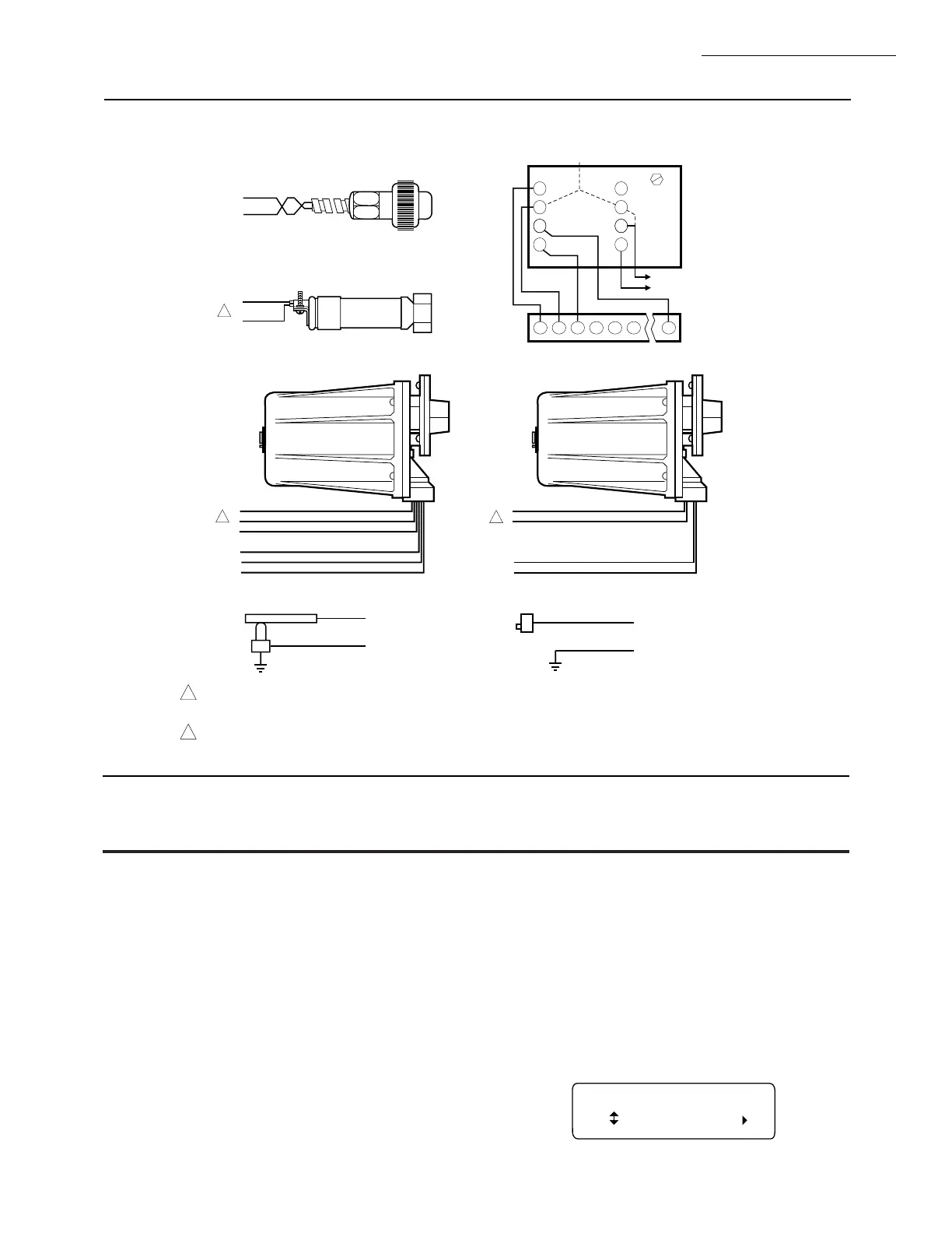
Fig. 23—Flame detector wiring.
M7800E,G,L,M
ASSEMBLY • OPERATION
M1969A
1
FLAME DETECTOR LEADS ARE COLOR CODED. THE BLUE LEAD MUST BE CONNECTED TO THE F TERMINAL AND THE WHITE
MUST BE CONNECTED TO THE G TERMINAL. THE UV SENSING TUBE IS POLARITY SENSITIVE. REVERSING THE LEADS EVEN
MOMENTARILY CAN DAMAGE OR DESTROY THE UV TUBE.
FLAME DETECTOR LEADS ARE COLOR CODED. THE BLUE LEAD MUST BE CONNECTED TO THE F TERMINAL AND THE YELLOW
MUST BE CONNECTED TO THE G TERMINAL. THE UV SENSING TUBE IS POLARITY SENSITIVE. REVERSING THE LEADS EVEN
MOMENTARILY CAN DAMAGE OR DESTROY THE UV TUBE.
2
BLUE
YELLOW
WHITE
WHITE
BLACK
BLACK
F
G
22
L2
L1
L2
BLUE
WHITE
F
G
WHITE
BROWN
F
G
INFRARED (C7015)
ULTRAVIOLET (C7027/C7035/C7044)
SOLID STATE SELF-CHECKING
ULTRAVIOLET (C7012E,F)
BLUE
YELLOW
BLACK
BLACK
F
G
L1
L2
SOLID STATE
ULTRAVIOLET (C7012A,C)
1
2
2
F G
4
5
3
L2
C7076A,D ULTRAVIOLET DETECTOR
5
22
6
SHUTTER
G
SHUTTER
F
1
8
2
7
7800 SERIES
L1
L2
3a
3b
REMOTE
SENSOR
2b
2a
EARTH
GROUND
C7076A
OR
C7076D
TERMINAL
BLOCK
L2 (COMMON)
L1 (HOT)
G
F
X
X
FLAME ROD
G
F
X
X
PHOTOCELL
Operation
Sequence of Operation
The RM7800 has the following operating sequences, see
Figs. 24, 25, 26, and Table 3.
INITIATE
The RM7800 enters the INITIATE sequence when the
Relay Module is powered. The RM7800 can also enter the
INITIATE sequence if the Relay Module verifies voltage
fluctuations of +10/-15% or frequency fluctuations of
+/-10% during any part of the operating sequence. The
INITIATE sequence lasts for ten seconds unless the voltage
or frequency tolerances are not met. When the tolerances
are not met, a hold condition will be initiated and will be
displayed on the VFD for at least five seconds. When the
tolerances are met, the INITIATE sequence will restart. If
the condition is not corrected and the hold condition exists
for four minutes, the RM7800 will lockout. Causes for hold
conditions in the INITIATE sequence:
a. AC line dropout is detected.
b. AC line frequency error caused by using a 60 Hz
device on a 50 Hz line, or vice versa.
c. AC line noise that can prevent a sufficient reading of
the line voltage inputs.
d. Brownouts caused by a low line voltage.
The INITIATE sequence also delays the burner motor
starter from being energized and de-energized from an
intermittent AC line input or control input.
INITIATE 00:10
Diagnostic Info
23 65-0117—2
 Loading...

