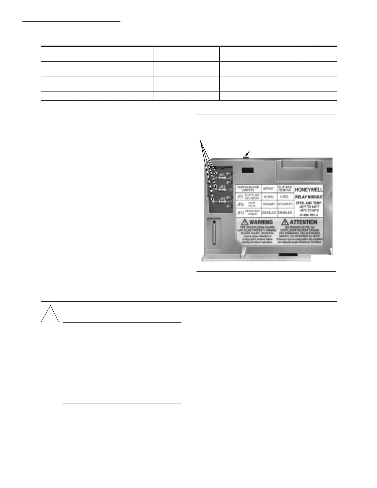
Fig. 32—Selectable site-configurable jumpers.
RM7800E,G,L,M
OPERATION • STATIC CHECKOUT
32
TABLE 6—SITE CONFIGURABLE JUMPER OPTIONS.
Jumper
Number Description Intact Clipped RM7800 Type
JR1 Pilot Flame Establishing
Period (PFEP) 10 Seconds 4 Seconds (All)
JR2 Pilot Valve
b
/Main Flame 10 Seconds Intermittent 15 or 30 Seconds Interrupted
a
(RM7800G)
Establishing Period (MFEP)
JR3 Start-up Interlock Check Disabled Enabled (All)
!
CAUTION
1. Use extreme care while testing the system. Line
voltage is present on most terminal connections
when power is on.
2. Open the master switch before installing or
removing a jumper on the subbase.
3. Before continuing to the next test, be sure to
remove test jumper(s) used in the previous test.
4. Replace all limits and interlocks that are not
operating properly. Do not bypass limits and
interlocks.
5. Close all manual fuel shutoff valve(s) before
starting these tests.
After checking all wiring, perform this checkout before
installing the RM7800 on the subbase. These tests verify
the Q7800 Wiring Subbase is wired correctly, and the exter-
nal controllers, limits, interlocks, actuators, valves, trans-
formers, motors and other devices are operating properly.
Static Checkout
NOTE: Do not perform a dielectric test with the RM7800
installed. Internal surge protectors will break down and
conduct a current. This could cause the RM7800 to fail
the dielectric test or possibly destroy the internal light-
ning and high current protection.
EQUIPMENT RECOMMENDED
1. Voltmeter (20 kohm/volt minimum sensitivity) set on
the 0-300 Vac scale.
2. Two jumper wires; no. 14 wire, insulated, 12 inches
[304.8 mm] long with insulated alligator clips at both ends.
GENERAL INSTRUCTIONS
1. Perform all applicable tests listed in Static Checkout,
Table 7, in the order listed.
2. Make sure all manual fuel shutoff valve(s) are closed.
3. Perform only those tests designated for the specific
RM7800 model being tested.
4. Raise the setpoint of the operating controller to simu-
late a call for heat.
a
A 30 second MFEP can be accomplished by adding a
jumper wire between terminals 19 and 5.
b
Pilot Valve /First Stage Oil Valve (Valv/Start) terminal 21.
SERVICE NOTE: Clipping and removing a site-con-
figurable jumper enhances the level of safety.
RUN/TEST SWITCH
SELECTABLE CONFIGURATION JUMPERS
M7398
 Loading...

