RM7898A 7800 SERIES VALVE PROVING PRIMARY RELAY MODULES
32-00209-03 14
Setup of Valve Proving and Post
Purge Functions
Prior to setup of the Valve Proving and Post Purge
functions, follow the procedures in the appendix to
complete the worksheet and obtain the Valve Proving Test
Time.
An S7800A1142 Keyboard Display Module (KDM) is required
for this setup and the RM7898 must have the Valve Proving
function.
When the RM7898 is installed and powered, “STANDBY”
will be shown on the first line of the display.
1. Scroll down until the “Setup” is displayed in the sec-
ond line. (Setup is only available when the control is
in Standby or Lockout state.)
Fig. 7. STANDBY/Setup screen.
2. Enter the Setup submenu by pressing the far right
key on the display. Note that the second line now
reads “BC Password”.
Fig. 8. Password screen.
3. Use the +/- buttons to enter the first number, 7.
4. Use the far right key to shift over one space.
5. Use the +/- buttons to enter the second number, 8.
6. Press Enter (left/right arrow simultaneously).
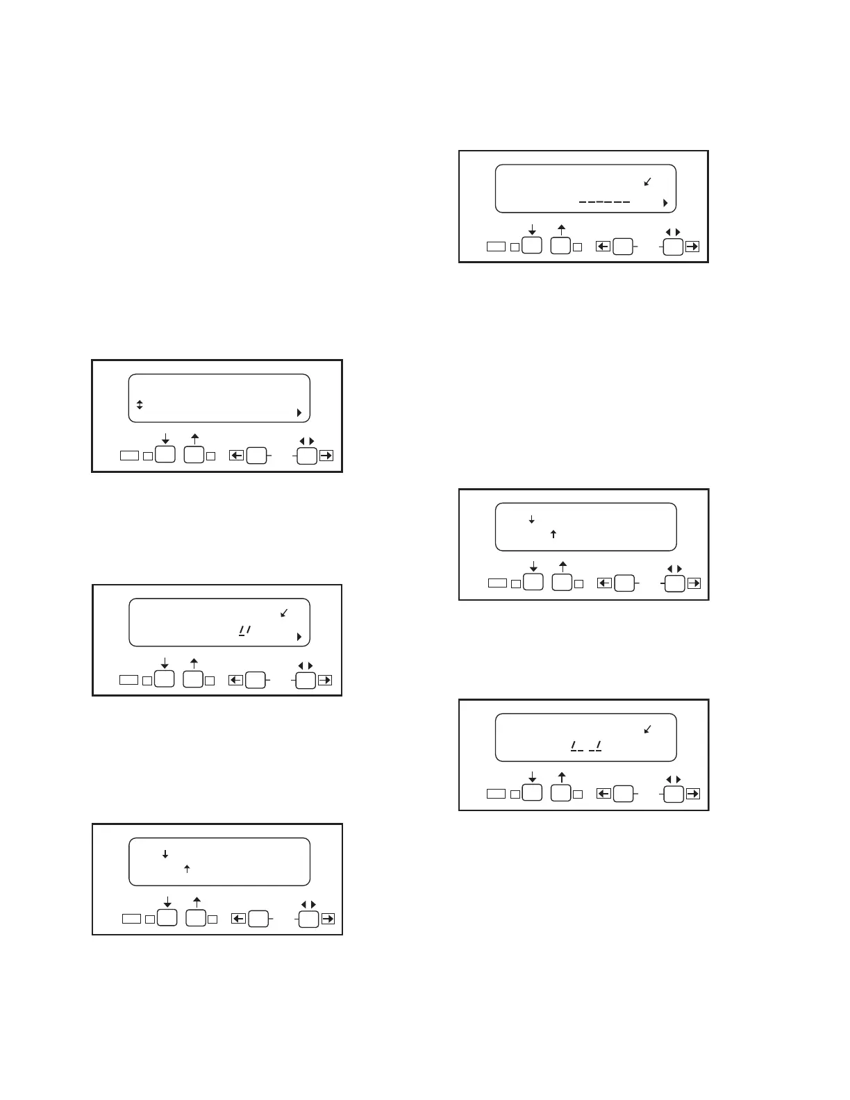
Fig. 9. Select/Restart screen.
7. To get to the next screen, press the down arrow. “Get-
ting Data” will be displayed, then the following
screen.
Fig. 10. SETUP: Valve Prove screen.
NOTE: This screen sets up when to do the Valve Proving
test.
8. Use the up/down arrows to select from Never,
Before, After, Both, or Split, then press ENTER.
NOTE: Use Never (as shipped) on initial startup so gas
line purging and System Checkout can be
performed. Then come back to set final operation
configuration. Be sure to conduct final VPS
System checkout when Setup is complete.
Fig. 11. Save Changes screen.
9. Use the down arrow to save changes. After pressing
the down arrow, “Getting Data” is displayed.
Fig. 12. Valve Prove time screen.
This screen sets up how long the RM7898 will conduct the
Valve Proving test for a given time. VP TIme: 00:00 is
shown.
10. Enter the appropriate Valve Proving test time from
the worksheet in the appendix.
Use the + button to increase and - button to
decrease time. Time changes:
a. 0 to 60 seconds in 1-second intervals.
b. 60 to 600 seconds in 10-second intervals.
c. 10 to 60 minutes in 1-minute intervals.
STANDBY
Setup
M22662B
BACK
ENTER
Edit:
-+
STANDBY
± BC Password: 00
M22663B
SU
BACK
ENTER
Edit:
-+
=Select
=Restart
M22764B
BACK
ENTER
Edit:
-+
SETUP: ValveProve
± VP When: BEFORE
M22664B
SU
BACK
ENTER
Edit:
-+
=Save changes
=Restart
M22665B
BACK
ENTER
Edit:
-+
SETUP: ValveProve
±VP Time: 00:00
M22666B
SU
BACK
ENTER
Edit:
-+
 Loading...
