S05, S10, S20 SERIES SPRING RETURN DIRECT COUPLED ACTUATORS
63-2607—08 4
Sizing
Required Torque
In lieu of data from a Specification Engineer or Manufacturer,
required torque for a given damper load can be determined
using the following method:
Where:
—T
R
= Required torque for the damper load.
—T
D
= Damper torque rating from the manufacturer,
expressed in either (lb-in.)/(sq ft) or (N•m)/(sq m). the
damper load.
—A
D
= Damper area expressed in either sq ft or sq m.
Actuators Required
In lieu of data from a Specification Engineer or Manufacturer,
the number of required actuators for a given damper load can
be determined using the following method:
Where:
— N = Number of actuators.
—T
R
= Required torque for the damper load. (See above.)
—T
A
= Actuator torque rating.
— SF = Safety factor.
NOTE: The safety factor accounts for variables such as mis-
alignments, aging of the damper, etc. 0.8 is a typical
safety factor.
INSTALLATION
When Installing this Product...
1. Read these instructions carefully. Failure to follow
them could damage the product or cause a hazardous
condition.
2. Check the ratings given in the instructions and on the
product to make sure the product is suitable for your
application.
3. Installer must be a trained, experienced service
technician.
4. After installation is complete, check out product
operation as provided in these instructions.
CAUTION
Electrical Shock or Equipment Damage Hazard.
Low voltage can shock individuals or short
equipment circuitry.
Disconnect power supply before installation.
IMPORTANT
All wiring must agree with applicable codes,
ordinances and regulations.
Location
These actuators are designed to mount directly to a damper
external drive shaft. The shaft coupling fastens to the drive
shaft. The actuator housing includes slots which, along with an
anti-rotation bracket, secure the actuator to the damper frame
or duct work (see Fig. 8).
NOTES:
— When mounted correctly, these slots allow the
actuator to float without rotating relative to the
damper shaft.
— Using other brackets or linkages, the actuator can
be foot-mounted or tandem-mounted.
CAUTION
Motor Damage Hazard.
Deteriorating vapors and acid fumes can damage
metal parts.
Install motor in areas free of acid fumes and other
deteriorating vapors.
CAUTION
Equipment Damage Hazard.
Tightly securing actuator to damper housing can
damage actuator.
Mount actuator to allow it to float along its vertical axis.
Preparation
Before mounting the actuator onto the damper shaft, determine
the:
— Damper/valve opening direction for correct spring return
rotation. The actuator can be mounted to provide clockwise
or counterclockwise spring return.
— Damper shaft size (see the Specifications section).
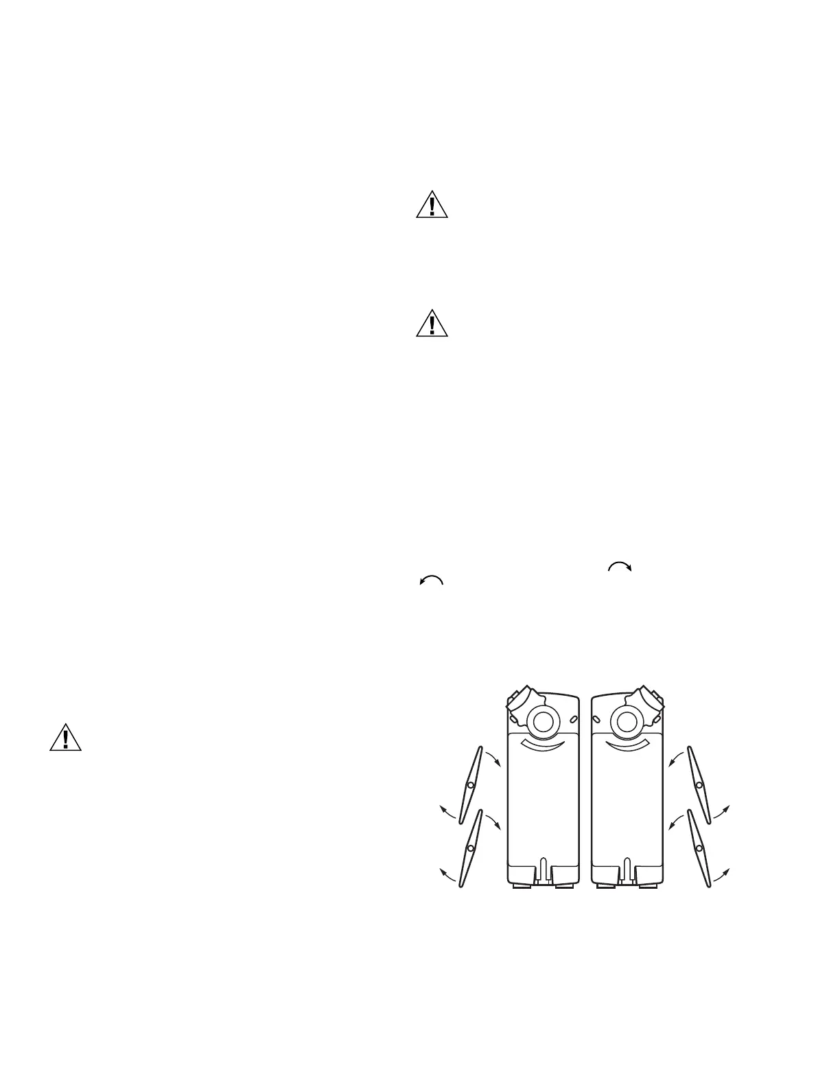
Determine Appropriate Mounting Orientation
The actuators are designed to open a damper by driving the
damper shaft in either a clockwise or counterclockwise
direction (see Fig. 2).
NOTES:
— Actuators are shipped in the fully closed (spring
return) position.
— An arrow molded into the hub points to tick marks
on the label to indicate the hub rotary position.
Fig. 2. Spring Return DCA mounting orientation.
Measure Damper/Valve Shaft Length
If the shaft is less than three inches in length, the shaft
coupling must be located between the damper/valve and
actuator housing. If the shaft length is more than three inches,
the shaft coupling may be located on either side of the actuator
housing.
T
R
T
D
A
D
×=
N
T
R
T
A
SF×
-------------------
=
M20953
CCW TO CLOSE
(FAIL-SAFE
POSITION)
CW TO OPEN
CW TO CLOSE
(FAIL-SAFE
POSITION)
CCW TO OPEN

 Loading...


