S05, S10, S20 SERIES SPRING RETURN DIRECT COUPLED ACTUATORS
63-2607—08 8
WIRING
CAUTION
Electrical Shock or Equipment Damage Hazard.
Disconnect all power supplies before installation.
Motors with auxiliary switches can have more than one
disconnect.
IMPORTANT
All wiring must comply with local electrical codes,
ordinances and regulations.
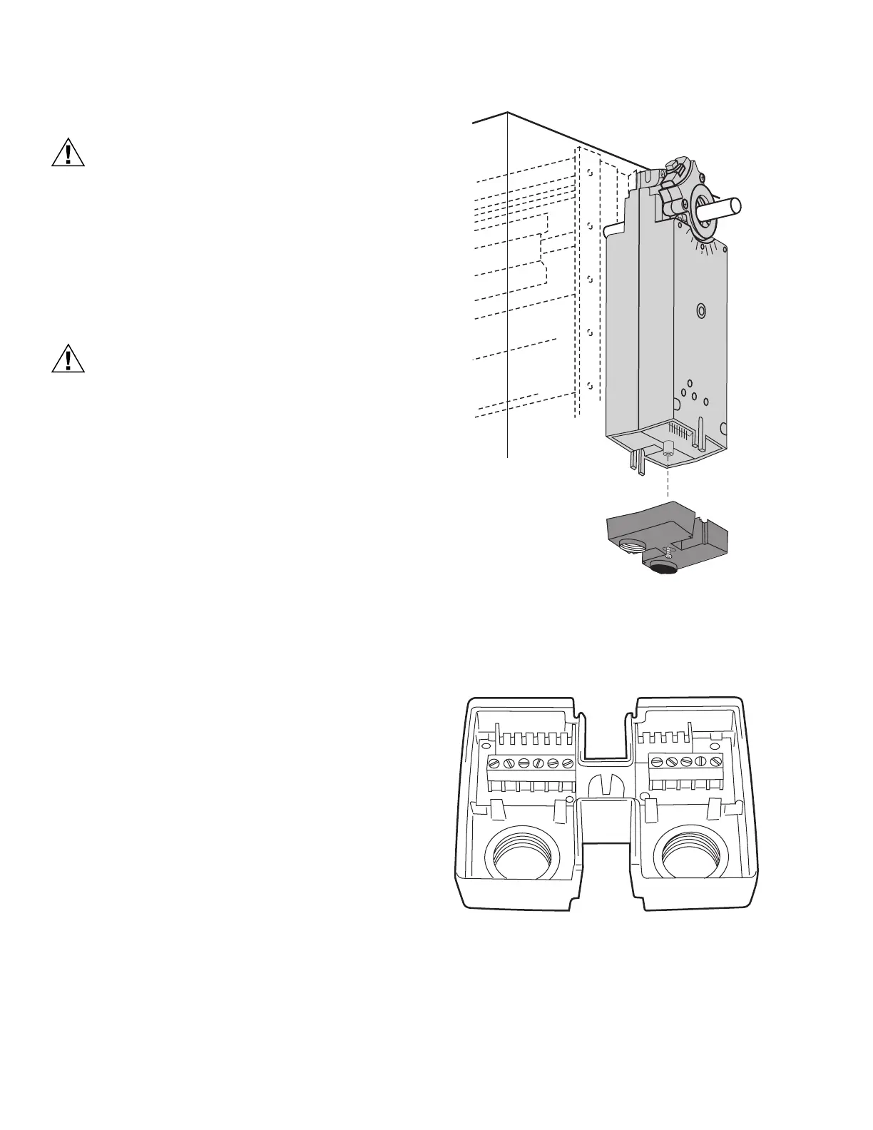
Access Cover Removal (Fig. 9)
CAUTION
Equipment Damage Hazard.
Improper cover removal can damage electric
connections.
Pull the cover along the axis of the actuator.
The cover contains contact sockets that must connect
to actuator contact pins.
Bending these pins can permanently damage the
device.
NOTE: This cover can be removed before or after actuator
mounting.
In order to wire the device, the access cover must be removed
as follows:
1. Remove the screw from the center of the cover, set the
screw aside.
2. Pull the cover along the long axis of the actuator.
3. If the actuator is not yet mounted, set it aside.
4. Remove conduit dust covers as necessary.
5. Thread wire through conduit holes.
6. Connect wires as appropriate to the terminal block(s).
(See Fig. 10 and 11.)
NOTE: With US Models, use 1/2 in. NPS strain relief
gland or 1/2 in. conduit adapters. Recommend
using flex conduit.
With European Models, use M16 strain relief
gland.
Fig. 9. Removing access cover.
Typical Wiring
See Fig. 10 through 26 for typical wiring details.
Fig. 10. Terminal block details.
M20957
1
234
5
1
2
34
5
S1 S2
S3 S4
S5
S6
M20958

 Loading...


