7800 SERIES S7800A KEYBOARD DISPLAY MODULE
65-009
0-6
10
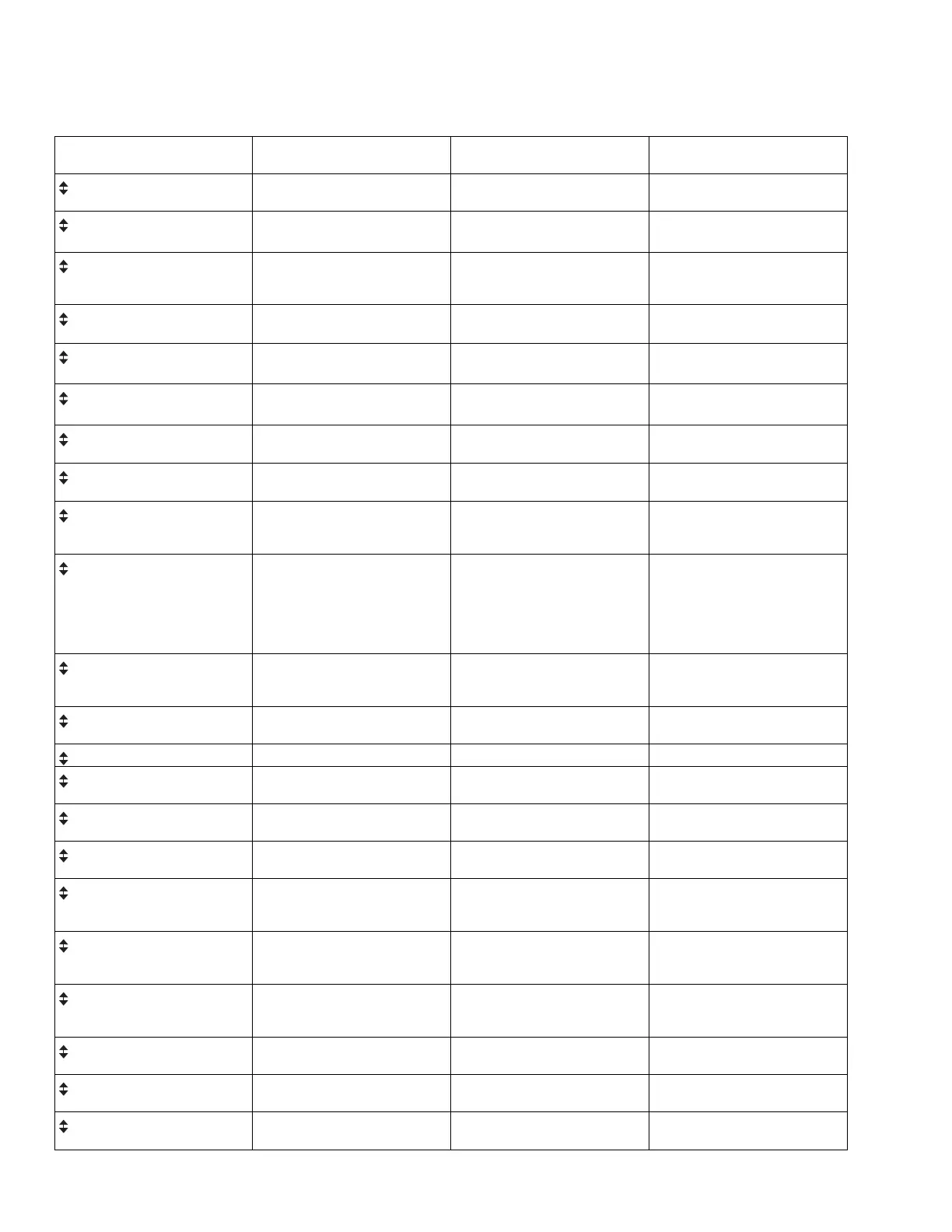
Table 3. Selectable Messages
.
Select
able
Message/Display
Description
Possible States/ Ra
nge
(T
ermina
ls
) Comments
Flame Signal
Flame signal strength. 0 - 5.0 Vdc Flame Amp ( and
- (Com))
Flame relay pull-in and drop-
out value 1.25 Vdc.
Total Cycles
Total number of equipment
operating cycles.
0 - 99,999
(250,000; 999,999
c
) cycles
a
Cycle will be updated each
time main valve is energized.
Total Hours
Total number of equipment
operating hours.
0 - 99,999
(250,000; 999,999
c
) hours
a
Hour will be updated each time
main valve output is energized
for 60 minutes.
Fault History >
(Six most recent faults)
First level prompt for history
information. Has subset level.
-
-
Fault Cycle
¡¿
H1
Cycle when fault occurred. 0 - 99,999 cycles (250,000;
999,999
c
) cycles
-
Fault Hours
¡¿
H1
Run hour when fault occurred. 0 - 99,999
(250,000; 999,999
c
) hours
a
-
Fault Code
¡¿
H1
Number that identifies the
reason for lockout.
0 - 999
-
*Fault Message*
¡¿
H1
Indicates cause of lockout.
-
-
Sequence Message
¡¿
H1
Indicates where in the
sequence the lockout
occurred.
-
-
(Second Line Message)
¡¿
H1
Second line message explains
any further information that is
available from the 7800
SERIES or may be blank if
there is not a preemptive
second-line.
H2.H6
etc.
-
-
Diagnostic Information >
First level prompt for
diagnostic information. Has
subset level.
-
-
Device
Device type number. RM78XXX, R7140, or
EC78XXX
-
Device Suffix
Device suffix number. nnnn
-
Run/Test Sw.
Position of Run/Test Switch. RUN or TEST Indicates if 7800 SERIES is in
RUN or TEST mode.
OperControl T6
Operating Control Input. = 1 or 0
Indicates if input is on or off,
energized or de-energized.
Interlock T7
Running/Lockout Interlock. = 1 or 0 Indicates if input is on (1) or off
(0), energized or de-energized.
Pilot Valve
T8 Pilot Valve. = 1 or 0
Indicates if output terminal is
on or off, energized or
de-energized.
Main Valve
T9 Main Fuel Valve. = 1 or 0
Indicates if output terminal is
on or off, energized or
de-energized.
Ignition
T10 Ignition. = 1 or 0
Indicates if output terminal is
on or off, energized or de-
energized.
LowFire Sw
T18 Low Fire Switch. = 1 or 0
Indicates if input is on or off,
energized or de-energized.
HighFireSw
T19 High Fire Switch. = 1 or 0
Indicates if input is on or off,
energized or de-energized.
PreIgn ILK T20 or T17
b
Pre-Ignition
Interlock
= 1 or 0
Indicates if input is on or off,
energized or de-energized.