S8600B,C,H,M; S8610B,C,H,M; S8670D,E,J,K INTERMITTENT PILOT GAS IGNITION CONTROL
บริษัท เอดีดี เฟอร์เนส จํากัด
ADD FURNACE CO.,LTD.
44 ซอยบรมราชชนนี 70 ถนนบรมราชชนนี แขวงศาลาธรรมสพน์ เขตทวีวัฒนา กรุงเทพฯ 10170
โทร: 02-888-3472 โทร: ออกแบบ:08-08-170-170 แฟกซ์: 02-888-3258
https://www.add-furnace.com E-mail: sales@add-furnace.com
—
Operating ambient temperatures between -40°F and 175°F (-
40°C and 79°C); (165°F [74°C] for S8610 and
S8670 models).
—
Relative humidity below 95% noncondensing.
—
Protection from water, steam or corrosive chemicals that are
used to clean the appliance.
—
Protection from dripping water, such as from an
overfilled humidifier or from condensation.
—
Protection from dust or grease accumulation.
Mount the Ignition Module
Select a location close enough to the burner to allow a short (3 ft.
[0.9 m] max.), direct cable route to the pilot burner. Ambient
temperature at the module must be within the range listed under
Operating Temperature, on page 2. The module must be protected
from water, moisture, corrosive chemicals and excessive dust and
grease.
Mount the module with the terminals down to protect them from
dripping water and dust. As an alternative, it can also be mounted
with the terminals on either side.
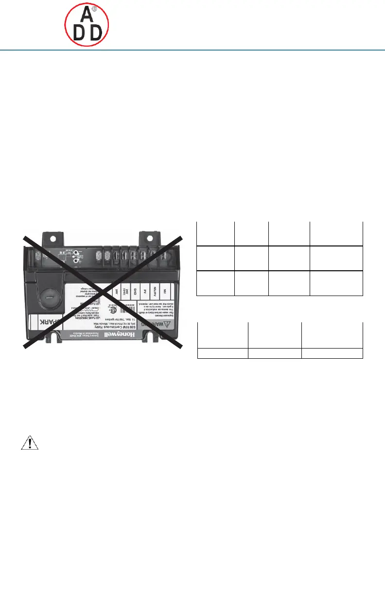
IMPORTANT
Do not mount with terminals facing up.
M29897
Fig. 1. Incorrect Mounting (Model S8600M shown).
Fasten securely with four No. 6-32 machine or No. 8 sheet metal
screws.
Mount the System Controls
Mount any required controls, such as the gas control, spark
igniter, flame sensor, thermostat, limit, and transformer according
to manufacturer’s instructions.
Wire the System
CAUTION
Equipment Damage Hazard.
Disconnect power supply before beginning wiring or
making wiring connections to prevent electrical shock or
equipment damage.
All wiring must comply with local codes and ordinances. See Fig. 2
and Table 4 for proper wiring connections.
IMPORTANT
1.
As shown in the wiring diagrams, a common ground
is required on:
aThe pilot burner mounting bracket, and bThe
GND(BURNER) terminal on the ignition
module. Failure to use the GND(BURNER) terminal
may result in intermittent loss of spark and/or loss of
flame current sensitivity.
2.
Make sure the transformer has adequate VA. The
ignition module requires at least 0.1 A at 24 Vac. Add the
current draws of all other devices in the control circuit,
including the pilot and main valves in the gas control,
and multiply by 24 to determine the total VA requirement
of these components. Add this total to 2.4 VA (for the igni-
tion module). The result is the minimum trans- former VA
rating. Use a Class II transformer if replacement is
required.
CONNECT IGNITION CABLE
Use Honeywell ignition cable or construct an ignition cable that
conforms to suitable national standards such as Underwriters
Laboratories Inc. See Table 2 and Table 3.
.
Table 2. Honeywell Pre-assembled Ignition Cables (UL
Style 3257).
1/4 inch quick
connect,
insulated
Rajah connector
receptacle, 90 degree
rubber boot
1/4 inch quick
connect,
insulated
Rajah connector
receptacle, straight
rubber boot
Table 3. Recommended Ignition Cable for Field
Assembly.
Cable must be no longer than 36 in. (0.9 m). Solid conductor cable
recommended. To construct a cable, fit one end of ignition cable with
1/4 in. diameter Rajah connector receptacle and the other with a 1/4
in. female quick connect. Protect both ends with insulated boots.
NOTE: The cable must not run in continuous contact with a metal
surface or spark voltage will be greatly reduced. Use
ceramic or plastic standoff insulators as required.
Resistive spark cable reduces spark voltage and may
impact appliance performance.
To install:
(1)
Connect one end of the cable to the male quick
connect SPARK terminal on the igni- tion module.
(2)
Connect the other end of the cable to the igniter
or igniter-sensor stud on the pilot burner/igniter-
sensor.
CONNECT IGNITION MODULE
NOTE: Refer to Fig. 2 and Table 4 for the location of each
connection.
 Loading...