S8600B,C,H,M; S8610B,C,H,M; S8670D,E,J,K INTERMITTENT PILOT GAS IGNITION CONTROL
บริษัท เอดีดี เฟอร์เนส จํากัด
ADD FURNACE CO.,LTD.
44 ซอยบรมราชชนนี 70 ถนนบรมราชชนนี แขวงศาลาธรรมสพน์ เขตทวีวัฒนา กรุงเทพฯ 10170
โทร: 02-888-3472 โทร: ออกแบบ:08-08-170-170 แฟกซ์: 02-888-3258
https://www.add-furnace.com E-mail: sales@add-furnace.com
ALARM2 (OPT)
24V
ALARM1 (OPT)
Connect remaining system components to the ignition
module terminals as shown in the appropriate wiring
diagram.
•
Fig. 3 is a basic circuit for the H and M models used in
heating systems with atmospheric burners.
•
Fig. 4 shows the basic circuit for the B and C models
with separate sensor and igniter in a heating system
with atmospheric burners.
•
Fig. 5—8 show typical circuits for power assisted
combustion applications and two-stage gas control
with power assisted combustion applications.
MAKE FLAME SENSE CONNECTION
For B, C, J, and K models:
These models have remote flame sensing (two rod).
Connect the flame sensor wire from the Pilot burner/
igniter to the SENSE connector on the ignition module.
For H, M, D, and E models:
These models have local flame sensing (single rod). The
spark lead carries the flame signal.
CONNECT GAS CONTROL
Use 18-gauge solid or stranded wire. Use 1/4 in. female
quick connects for module connections. Connect to gas
control terminals as shown in wiring diagrams, using
terminals appropriate to the gas control.
GROUND CONTROL SYSTEM
The igniter, flame sensor and ignition module must share
a common ground with the pilot burner. Use thermoplastic
insulated wire with a minimum rating of 221°F (105°C) for
the ground wire; asbestos insulation is not acceptable. If
necessary, use a shield to protect the wire from radiant
heat generated by the burner. Connect the ground wire as
follows:
1.
Fit one end of the ground wire with a female 1/4 in.
quick-connect terminal and connect it to the male
quick-connect BRN GND terminal on the ignition
module.
2.
Strip the other end of the wire and fasten it under
the pilot burner bracket mounting screw. If neces-
sary, use a shield to protect the ground wire from
radiant heat.
3.
The pilot burner serves as the common grounding
area. If there is not good metal-to-metal contact
between the pilot burner and ground, run a lead
from the pilot burner to ground.
NOTE: Earth ground is not required.
Table 4. Wiring Connection Descriptions.
Common terminal for gas
valve
Return path to transformer
Alarm connection
(optional for B, H, D, and J
models only)
Alarm connection
(optional for B, H, D, and J
models only)
Connection for ammeter
probes for measuring flame
current in
Amp DC.
Flame Sensor
(B, C, J, and K models Only)
High voltage sparking
electrode
S8600 H,M; S8610 H,M
1
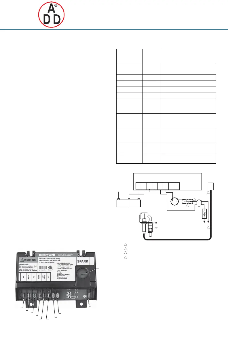
POWER SUPPLY. PROVIDE DISCONNECT MEANS AND OVERLOAD PROTECTION AS REQUIRED.
2
ALTERNATE LIMIT CONTROLLER LOCATION.
3
MAXIMUM CABLE LENGTH 3 FT. [0.9 M].
4
CONTROLS IN 24V CIRCUIT MUST NOT BE IN GROUND LEG TO TRANSFORMER.
Fig. 3. S8600 H,M; S8610 H,M; connections in a
heating system with an atmospheric burner.
M29899
PARK
29898
Fig. 2. Ignition Module wiring connection locations
(Model S8610B shown).
GND 24V
MV MV/PV PV
(BRN) GND
24V
OPERATOR OPERATOR
DUAL VALVE COMBINATION
GAS CONTROL
PILOT BURNER/
IGNITER-SENSOR
 Loading...