COMPACT VAV CONTROLLER WEB-VA423B24N – INSTALLATION INSTRUCTIONS
31-00362-01 4
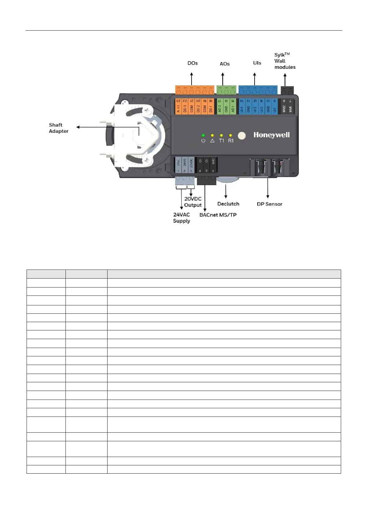
TERMINALS
Table 4. WEB-VA423B24N: Overview of the terminals and functions
Supply Voltage (GND), internally connected with terminal 10, 13 & 16
Removable BACnet MS/TP interface
Shield for external wiring support. It is not connected internally.
Removable interface for Sylk™ bus
Supply voltage common terminal for DO. It is internally connected to terminal
21 but not to the controller's GND terminal.
Supply voltage common terminal for DO. It is internally connected to terminal
19 but not to the controller's GND terminal.
24V AC/DC input for DOs 1-3
Fig. 3. WEB-VA423B24N: Overview of terminals and functions

 Loading...