SPYDER® LON PROGRAMMABLE, VAV/UNITARY CONTROLLERS
11 63-2685—03
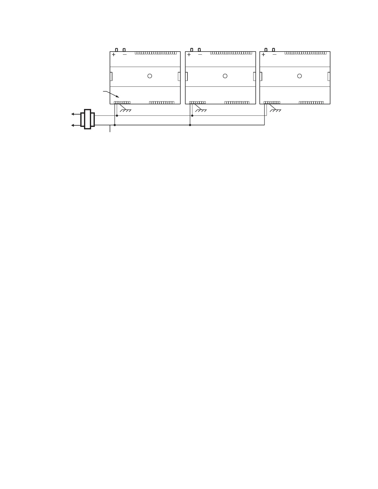
Fig. 13. Power wiring details for two or more controllers per transformer.
Communications
Refer to “LONWORKS® Wiring Guidelines,” form 74-2865, for a
complete description of L
ONWORKS® Bus network topology
rules and approved cable types.
Honeywell provided cable types for L
ONWORKS® Bus
communications wiring are Level IV 22 AWG (0.34 sq mm)
plenum or non-plenum rated unshielded, twisted pair, stranded
conductor wire.
• For non-plenum areas, U.S. part AK3798 (single-pair
stranded) can be used.
• In plenum areas, U.S. part AK3797 (single-pair stranded) or
U.S. part AK3799 (two-pair stranded) can be used.
Contact Echelon Corp. Technical Support for the
recommended vendors of Echelon approved cables.
Communications wiring can be run in a conduit, if needed, with
non-switched 24 Vac or sensor wiring. If a longer L
ONWORKS®
Bus network is required, a Q7751A,B router (configured as a
repeater) can be added to extend the length of the
L
ONWORKS® Bus. Each network segment can have a
maximum of one repeater.
Pull the cable to each controller on the L
ONWORKS® Bus and
connect to the controller’s communication terminals 7 and 8.
(See Table 6 on page 13 and Table 7 on page 13, and Fig. 16
on page 14 for location of terminals 7 and 8.)
NOTE: Connection for operator access to the L
ONWORKS®
Bus is provided by plugging the Serial L
ONTALK®
Adapter (SLTA) connector into the L
ONWORKS® Bus
jack (see Fig. 16 on page 14).
IMPORTANT
Notes on communications wiring:
• All field wiring must conform to local codes and
ordinances (or as specified on installation drawings).
• Do not bundle device output wires with sensor, digital
input or communications L
ONWORKS® Bus wires.
• Do not use different wire types or gauges on the
same LONWORKS Bus segment. The step change in
line impedance characteristics causes unpredictable
reflections on the LONWORKS® Bus.
• In noisy (high EMI) environments, avoid wire runs
parallel to noisy power cables, motor control centers,
or lines containing lighting dimmer switches. Keep at
least 3 in. (76 mm) of separation between noisy lines
and the L
ONWORKS® Bus cable.
• The theoretical limit for each L
ONWORKS® Bus seg-
ment is 60 controllers. Up to 120 controllers can be
configured when a repeater is used, and the bus must
be either singly or doubly terminated. Actual installa-
tions may have a lower limit depending on the
devices connected.
• The singly terminated bus must have one 209541B
FTT Termination Module for T tap or Star configura-
tions.
• The doubly terminated bus must have two 209541B
FTT Termination Modules, one at each end of the
daisy chain (Bus style) wiring run. Note that the
Q7751A,B router (configured as a repeater) has
onboard terminating networks that can be jumper-
selected on each segment.
• Make sure that neither of the L
ONWORKS® Bus wires
are grounded.
NOTE: If a 209541B Termination Module is required at the
controller, connect two of the three termination
module wires to the L
ONWORKS® Bus terminals 7 and
8, which are labeled Net-1 and Net-2, on the
controller. Selecting the appropriate two wires
depends on the L
ONWORKS® Bus network topology.
Refer to the “L
ONWORKS® Bus Wiring Guidelines,”
form 74-2865, and the “FTT Termination Module
Installation Instructions,” form 95-7554. For example,
on a doubly terminated daisy-chained bus topology,
where controllers are on either end of an L
ONWORKS®
Bus wire run, mount the termination module on the
appropriate terminals, as shown in Fig. 14.
M23559A
120/240
VAC
TRANSFORMER
OUTPUT
DEVICE
POWER
ΔP
1
2
3 4 5 6
7 8
1 0 9 2 3 4 5 6 7 8 0 9
1 1 1 1 1 1 1 1 1 2 1
1
2
3 4
5
6
7 8
0
9
2
2 2
2 2
2
2
2 2
3
3
1
2
3 4
5
6
7 8
0
9
3
3
3
3 3
3 3
3 4
COM
24 VAC
ΔP
1
2
3 4 5 6
7 8
1 0 9 2 3 4 5 6 7 8 0 9
1 1 1 1 1 1 1 1 1 2 1
1
2
3 4
5
6
7 8
0
9
2
2 2
2 2
2
2
2 2
3
3
1
2
3 4
5
6
7 8
0
9
3
3
3
3 3
3 3
3 4
EARTH
GROUND (TERMINAL 3)
ΔP
1
2
3 4 5 6
7 8
1 0 9 2 3 4 5 6 7 8 0 9
1 1 1 1 1 1 1 1 1 2 1
1
2
3 4
5
6
7 8
0
9
2
2 2
2 2
2
2
2 2
3
3
1
2
3 4
5
6
7 8
0
9
3
3
3
3 3
3 3
3 4
EARTH
GROUND (TERMINAL 3)
EARTH
GROUND (TERMINAL 3)
CONNECT POWER TO
TERMINALS 1 AND 2

 Loading...