4
Notes
1. DT92E is completely wireless and so is not shown connected on
these wiring diagrams.
2. The ST9520C is a Class II (double insulated) device. A parking
terminal is provided for earth wiring continuity, if required.
3. The OpenTherm boiler connection (diagram 95-2) is a low voltage
polarity-free connection and is not for 230V~ mains voltages.
4. The BDR91T Relay Box (diagrams 95-3) requires a permanent
230V~ supply.
1.6 Wiring Diagrams
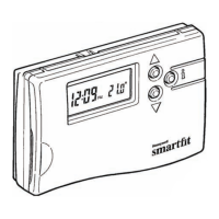
1.5 ST9520C Internal Wiring
Clock
N L 1 2 3 4
3 AMPS MAX
Zone1
OFF
Zone2
OFF
Zone1
ON
Zone2
ON
N
L
OFF ON OFF ON
230V~
50...60Hz
A B
OpenTherm low voltage
output to boiler.
NOT MAINS
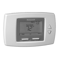
95-1 Wireless room thermostat, wired valves, wired TPI boiler control
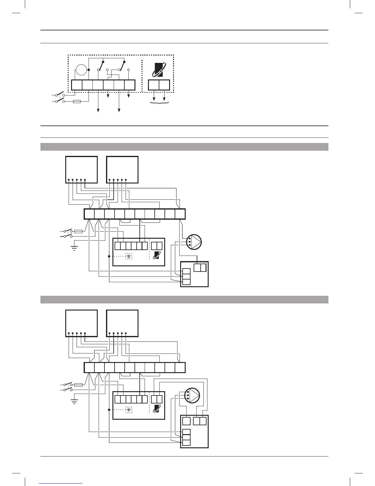
95-2 Wireless room thermostat, wired valves, OpenTherm 2 wire boiler control
V4043H
2 PORT ZONE VALVE
ZONE 2
BLUE
G/YELLOW
BROWN
ORANGE
GREY
V4043H
2 PORT ZONE VALVE
ZONE 1
BLUE
G/YELLOW
BROWN
ORANGE
GREY
3 AMPS
MAX
L
N
230V~
50...60Hz
BOILER
PUMP
L
N
E
ST9520C
*NOTE 2
N
L 1 2 3 4
A
B
T1
L
N
E
1 2 3 4 5 6 7 8 9 10
V4043H
2 PORT ZONE VALVE
ZONE 2
BLUE
G/YELLOW
BROWN
ORANGE
GREY
V4043H
2 PORT ZONE VALVE
ZONE 1
BLUE
G/YELLOW
BROWN
ORANGE
GREY
3 AMPS
MAX
L
N
230V~
50...60Hz
BOILER
PUMP
L
N
E
ST9520C
*NOTE 2
N
L 1 2 3 4
A
B
T1
T2
PL
L
N
E
1 2 3 4 5 6 7 8 9 10
Additional notes
a. Orange wires from zone valves are ‘parked’ for
convenience.
b. Pump live is taken from boiler. If boiler does not
provide this output, connect live input to pump from
terminal 10
 Loading...