SYLK™ I/O DEVICES
7 31-00028—02
NOTE: Controller and device configurations are not nec-
essarily limited to three devices, but the total
power draw, including accessories, cannot exceed
100 VA when powered by the same transformer
(U.S. only). For power wiring recommendations,
see “Power” on page 3.
Fig. 6. Power wiring details for two or more controllers and devices per transformer.
Communications
Sylk
™
Bus
Sylk is a two wire, polarity insensitive bus that provides
both 18 VDC power and communications between a Sylk-
enabled sensor, Sylk-enabled device, and a Sylk-enabled
controller. Using Sylk-enabled sensors and devices saves
I/O on the controller and is faster and cheaper to install
since only two wires are needed and the bus is polarity
insensitive. Sylk sensors and devices are configured using
the latest release of the Spyder Tool for WEBPro and
WEBStation. Using 18 AWG wire, the maximum wire
length for Sylk is 200 ft.
For Spyders and Sylk IO devices, use the Resource Usage
View in the Spyder tool to determine the maximum
number of devices.
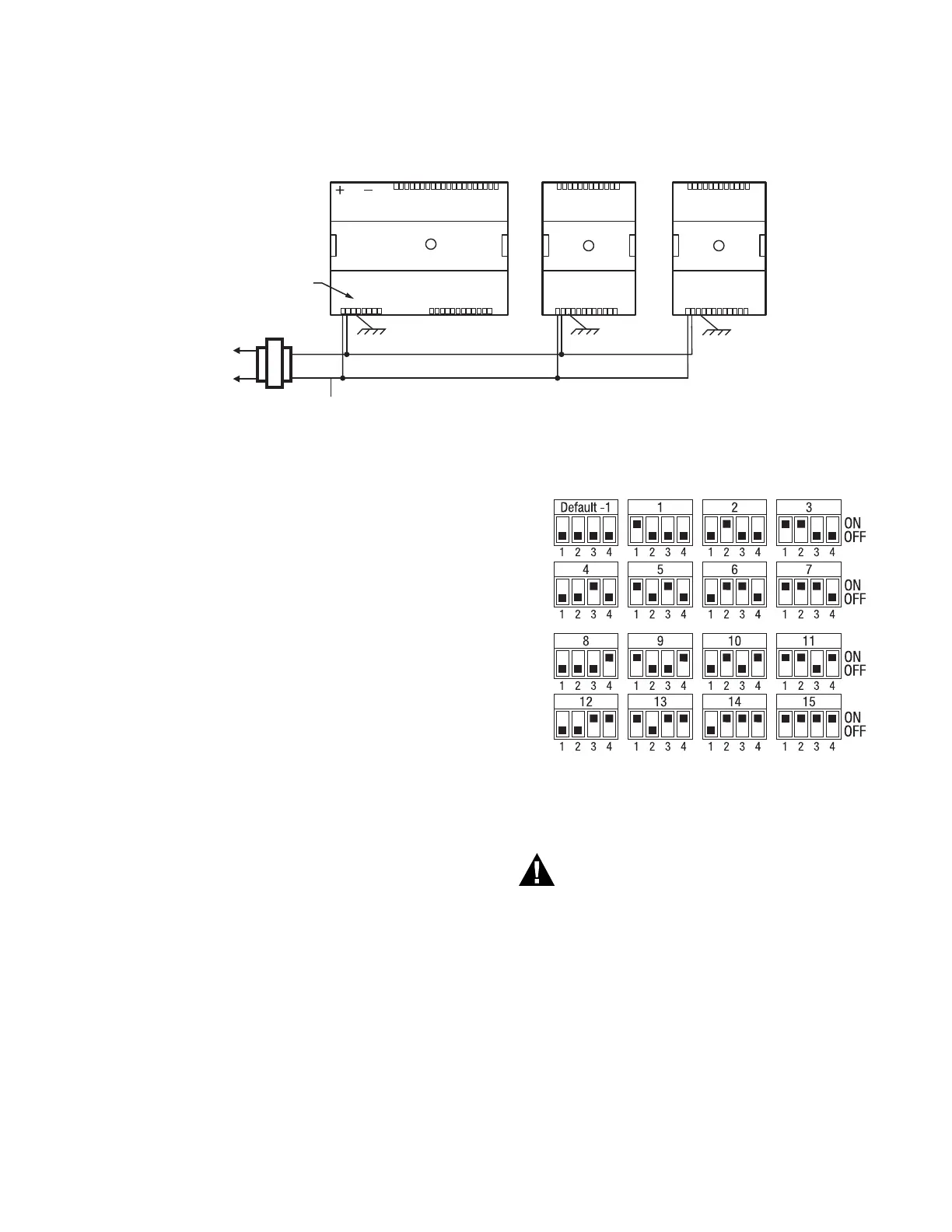
Setting the Device Bus Address Dial
Each device on a Sylk bus must use a different bus
address, and there may be multiple Sylk IOs wired on a
single Sylk bus. To change the bus address of a device,
adjust the address dipswitches to match that of the
desired bus address (1–15). Use the bus address label,
shown in Fig. 7, as a reference. The default address for
Sylk IOs is 1. The address on the device must match the
address in the configuration tool.
Fig. 7. Bus address settings.
Wiring Method
Electrical Shock Hazard.
Can cause severe injury, death or property
damage.
Disconnect power supply before beginning wiring,
or making wiring connections, to prevent electrical
shock or equipment damage.
NOTE: When attaching two or more wires to the same
terminal, other than 14 AWG (2.0 sq mm), be
sure to twist them together. Deviation from this
rule can result in improper electrical contact (see
Fig. 8).
Each terminal can accommodate the following gauges of
wire:
— Single wire: from 22 AWG to 14 AWG solid or stranded
M35143
120/240
VAC
TRANSFORMER
OUTPUT
DEVICE
POWER
1
2
3456
78
109 2345678 09
11 1111111 21
1
2
34
5
6
78
0
9
2
22
22
2
2
22
3
3
1
2
34
5
6
78
0
9
3
3
3
33
33
34
COM
24 VAC
321 4567890 21
111
3
4
56
7
8
90
2
1
1
11
11
1
1
22
2
2
3
4
2
EARTH
GROUND
(TERMINAL 3)
EARTH
GROUND
(TERMINAL 3)
EARTH
GROUND
(TERMINAL 3)
CONNECT POWER TO
TERMINALS 1 AND 2
321 4567890 21
111
3
4
56
7
8
90
2
1
1
11
11
1
1
22
2
2
3
4
2
M35180
 Loading...


