SYLK™ I/O DEVICES
31-00028—02 8
— Multiple wires: up to two 18 AWG stranded, with 1/4
watt wire-wound resistor
Prepare wiring for the terminal blocks, as follows:
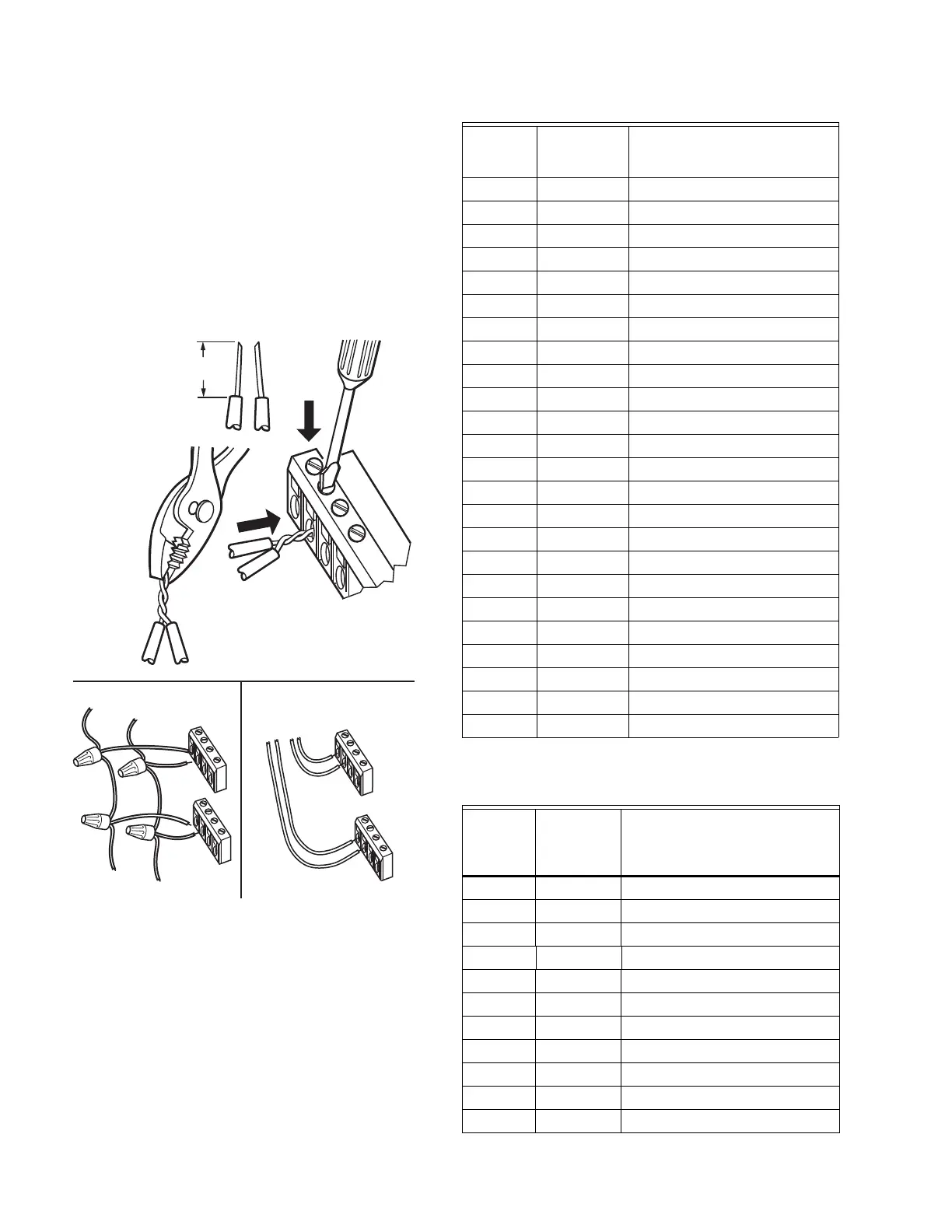
1. Strip 1/2 in. (13 mm) insulation from the conductor.
2. Cut a single wire to 3/16 in. (5 mm). Insert the wire in
the required terminal location and tighten the screw.
3. If two or more wires are being inserted into one ter-
minal location, twist the wires together a minimum
of three turns before inserting them (see Fig. 8).
4. Cut the twisted end of the wires to 3/16 in. (5 mm)
before inserting them into the terminal and tighten-
ing the screw.
5. Pull on each wire in all terminals to check for good
mechanical connection.
Fig. 8. Attaching two or more wires at terminal blocks.
Wiring Details
Each device is shipped with the digital outputs, which
switch the 24 Vac to the load (High Side).
The analog outputs (AO) are used to control modulating
heating, cooling and economizer equipment. Any AO may
be used as a digital output, as follows:
— False (0%) produces 0 Vdc, (0 mA)
— True (100%) produces the maximum 11 Vdc (22 mA)
TO CONTROLLER
DAISY-CHAINING MULTIPLE SYLK IOS HOME RUNNING MULTIPLE SYLK IOS
TO CONTROLLER
TO SYLK IO
M35403
1/2
(13)
STRIP 1/2 IN. (13 MM)
FROM WIRES TO
BE ATTACHED AT
ONE TERMINAL.
1.
2.
TWIST WIRES
TOGETHER WITH
PLIERS (A MINIMUM
OF THREE TURNS).
3.
CUT TWISTED END OF WIRES TO 3/16 IN.
(5 MM) BEFORE INSERTING INTO TERMINAL
AND TIGHTENING SCREW. THEN PULL ON
EACH WIRE IN ALL TERMINALS TO CHECK
FOR GOOD MECHANICAL CONNECTION.
SIO4022
Terminal
s Label Connection
1 24VAC 24VAC Power
2 24VAC COM 24VAC-COMMON
3 EGND Chassis/Earth Ground
4 N/A Not Applicable
5S-BUSSylk
6S-BUSSylk
7 N/A Not Applicable
8 N/A Not Applicable
9 N/A Not Applicable
10 DO-1 Discrete Triac Output
11 COM DO COMMON
12 DO-2 Discrete Triac Output
13 N/A Not Applicable
14 N/A Not Applicable
15 N/A Not Applicable
16 AO-2 Analog Output
17 COM AO COMMON
18 AO-1 Analog Output
19 UI-4 Universal Input
20 COM UI COMMON
21 UI-3 Universal Input
22 UI-2 Universal Input
23 COM UI COMMON
24 UI-1 Universal Input
Table 6. Description of wiring terminal connections for
SIO12000.
SIO1200
0
Terminal
s Label Connection
1 24VAC 24VAC Power
2 24VAC 24VAC-COMMON
3 EGND Chassis/Earth Ground
4 N/A Not Applicable
5S-BUSSylk
6S-BUSSylk
7UI-1Universal Input
8COMUI COMMON
9UI-2Universal Input
10 UI-3 Universal Input
11 COM UI COMMON
 Loading...


