SYLK™ I/O DEVICES
9 31-00028—02
IMPORTANT
If the device is not connected to a good earth
ground, the device's internal transient protection
circuitry is compromised and the function of
protecting the device from noise and power line
spikes cannot be fulfilled. This could result in a
damaged circuit board and require replacement of
the device. Refer to installation diagrams for
specific wiring.
CHECKOUT
Step 1. Check Installation and Wiring
Inspect all wiring connections at the device terminals, and
verify compliance with installation wiring diagrams. If any
wiring changes are required, first be sure to remove power
from the controller before starting work. Pay particular
attention to:
— 24 Vac power connections. Verify that multiple devices
being powered by the same transformer are wired with
the transformer secondary connected to the same
input terminal numbers on each device. Use a meter to
measure 24 Vac at the appropriate terminals (see Fig. 6
on page 7). Device configurations are not necessarily
limited to three devices, but the total power draw,
including accessories, cannot exceed 100 VA when
powered by the same transformer (U.S. only).
— Be sure that each device has terminal 3 wired to a
verified earth ground, using a wire run as short as
possible with the heaviest gauge wire available, up to
14 AWG (2.0 sq mm) with a minimum of 18 AWG (1.0 sq
mm) for each controller in the group (see Fig. 6 on
page 7).
— Verify that Triac wiring of the digital outputs to external
devices uses the proper load power and 24 Vac
common terminal (digital output common terminals)
for High-Side switching.
NOTE: All wiring must comply with applicable electrical
codes and ordinances or as specified on installa-
tion wiring diagrams.
For guidelines for wiring run lengths and power budget,
see “Power” on page 3.
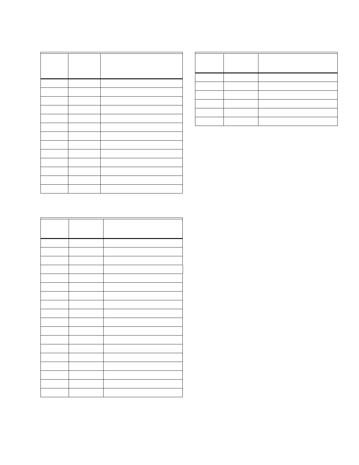
12 UI-4 Universal Input
13 UI-12 Universal Input
14 COM UI COMMON
15 UI-11 Universal Input
16 UI-10 Universal Input
17 COM UI COMMON
18 UI-9 Universal Input
19 UI-8 Universal Input
20 COM UI COMMON
21 UI-7 Universal Input
22 UI-6 Universal Input
23 COM UI COMMON
24 UI-5 Universal Input
Table 7. Description of wiring terminal connections for
SIO6042.
SIO6042
Terminal
s Label Connection
1 24VAC 24VAC Power
2 24VAC COM 24VAC-COMMON
3 EGND Chassis/Earth Ground
4 N/A Not Applicable
5S-BUSSylk
6S-BUSSylk
7 UI-1 Universal Input
8 COM UI COMMON
9 UI-2 Universal Input
10 DO-1 Discrete Triac Output
11 COM DO COMMON
12 DO-2 Discrete Triac Output
13 AO-4 Analog Output
14 COM AO COMMON
15 AO-3 Analog Output
16 AO-2 Analog Output
17 COM AO COMMON
18 AO-1 Analog Output
Table 6. Description of wiring terminal connections for
SIO12000. (Continued)
SIO1200
0
Terminal
s Label Connection
19 UI-6 Universal Input
20 COM UI COMMON
21 UI-5 Universal Input
22 UI-4 Universal Input
23 COM UI COMMON
24 UI-3 Universal Input
Table 7. Description of wiring terminal connections for
SIO6042.
SIO6042
Terminal
s Label Connection
 Loading...


