You will next be prompted to setup the thermostat with or without the mobile app. Select NO to continue setup
without using the Honeywell Home app. Select YES to continue setup using the Honeywell Home app. (Setup and
Configuration using the Honeywell Home App can be found under the WiFi and Connectivity support article)
Setup without the Honeywell Home App:
Use the < and > buttons to navigate the menu. Touch EDIT to modify each setting. When Finish Setup is displayed,
Touch SELECT to save the settings.
After Saving the configuration settings, you will be prompted to connect to Wi-Fi. If you Opt out of connecting to Wi-
Fi, you will be prompted to enter the time and date. You will then be able to operate your thermostat manually.
Reconfiguring your thermostat:
At any time, the configuration of your thermostat can be modified from the Installer Setup Menu.
Touch and hold the MENU button on the thermostat display. When DEVICE SETUP is displayed, touch SELECT.
Use the < and > buttons to navigate the menu. Touch EDIT to modify each setting. When Finish Setup is displayed,
Touch SELECT to save the settings.
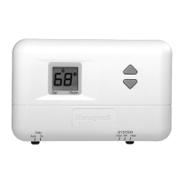
How do I wire my thermostat?
*There is no standard for which color wire controls each function. When wiring, each wire should be identified by
what terminal(s) it connects to, never by color. If you do not know the terminal that each wire connects to, it may be
necessary to go to the HVAC system and look at the designations on the control board. For typical wiring examples,
and for clarification of what types of systems your thermostat works with, please consult your owners/install guide. *
The thermostat uses 1 wire to control each of your HVAC system’s primary functions, such as heating, cooling, fan,
etc. See the diagram below for what each wire controls on your system:
S – Indoor and Outdoor Wired Sensors
Y – Compressor Stage 1 (Cooling)
Y2 – Compressor Stage 2 (Cooling)
G – Fan
C – Common
U – Humidifier, Dehumidifier, or Ventilator control
L/A – A – Input for heat pump fault
O/B – Reversing valve for Heat Pump systems
E – Emergency Heat
Aux / W2 – Heat Stage 2 (Heating)
W – Heat Stage 1 (Heating)
R – 24vac (Heating transformer)
Rc – 24vac (Cooling transformer)
*Trade model thermostats are required to operate “dual-fuel” systems (systems that use a heat pump for the first 1 or
2 stages of heating and use a gas or oil furnace for backup / emergency heating). If you have a dual-fuel system, or
are unsure, it is recommended that you contact a Professional HVAC Contractor to continue.
Please follow the below guide for the basic wiring walkthrough:
To protect your equipment, turn off the power at the breaker box or switch that controls your heating and cooling
equipment. To make sure that your system is off, change the temperature on your existing thermostat so that your
 Loading...