Do you have a question about the Honeywell T6811DP08 and is the answer not in the manual?
| Type | Digital |
|---|---|
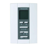
| Display Type | LCD |
| Mounting | Wall-mounted |
| Output | Relay |
| Stages | 1 Heat / 1 Cool |
| Backup Battery | No |
| Control Mode | Cooling, Heating |
| Application | Residential |
| Voltage | 24 VAC |
| Temperature Range | 40°F to 99°F (4°C to 37°C) |
| Set Point Range | 40°F to 99°F (4°C to 37°C) |
Electrical hazard alert for shock or equipment damage. Disconnect power before installation.
Lists and explains the function of each terminal on the thermostat.
Illustrates typical wiring configurations for ON/OFF control of HVAC systems.
Pull wires through the wallplate and place the back cover over the junction box.
Insert mounting screws, tighten, and connect wires to terminal blocks.
Align thermostat top with back cover, push down, and secure with a locking screw.
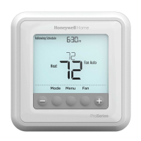
Enter setup by holding UP/MODE, change settings with UP/DOWN, advance with MODE.
Covers System Type, Temperature Scale, CPH values, Display adjustments, and ranges.
Hold UP and MODE buttons simultaneously to exit and save settings.
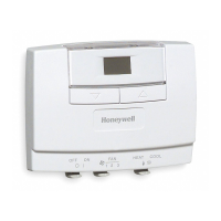
Slide the POWER switch to enter or exit the On/Off mode.
Use the FAN switch to select Low, Medium, or High fan speed.
Press MODE button to select Heat, Cool, or Vent mode.
Use UP or DOWN buttons to select desired temperature in Heat/Cool or Vent modes.
Check mode, temperature setting, and heat icon if the heating system does not start.
Verify mode, temperature setting, and cooling icon if the cooling system does not start.
Troubleshoot unresponsive mode, up, or down buttons by checking keypad lock and thermostat power.