T7200D,E, T7300D,E,F AND Q7300 SERIES 2000 PROGRAMMABLE COMMERCIAL THERMOSTATS AND SUBBASES
63-4355—27
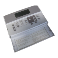
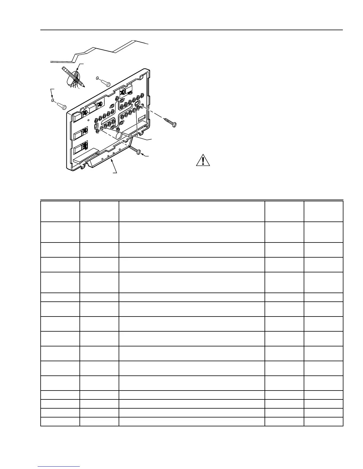
Fig. 8. Mounting subbase or wallplate.
WIRES
THROUGH WALL
WALL
WALL
ANCHORS
(2)
M10237
LEDS
MOUNTING
HOLES
MOUNTING
SCREWS
3. Remove the subbase or wallplate from the wall and drill
two 3/16 inch holes in the wall (if drywall) as marked.
For firmer material such as plaster or wood, drill two
7/32 inch holes. Gently tap anchors (provided) into the
drilled holes until flush with the wall.
4. Position the subbase or wallplate over the holes, pulling
wires through the wiring opening.
5. Loosely insert the mounting screws into the holes.
6. Tighten mounting screws.
WIRING SUBBASE OR WALLPLATE
All wiring must comply with local electrical codes and
ordinances. Follow equipment manufacturer wiring
instructions when available. Refer to Fig. 19 through 32 for
typical hookups. A letter code is located near each terminal
for identification. Refer to Table 6 for terminal designations.
CAUTION
Electrical Shock Hazard.
Power supply can cause electrical shock.
Disconnect power before beginning installation.
Table 6. Terminal Designations and Descriptions.
(continued)
Standard
Terminal
Designations
Alternate
Terminal
Designations Typical Connection Function
Terminal
Type
A1
A2
a
Dry auxiliary contacts for economizer control; A1 is
normally open during Unoccupied periods and closed
during Occupied periods.
Output Dry contact
A1, A2 — Damper control relay (Q7300L only). Input, Output 24V powered
contact
A2
A1
a
Dry auxiliary contacts for economizer control (A2 is
common).
Input Dry contact
A3 — Dry auxiliary contacts for economizer control; A3 is
normally open during Occupied periods and closed during
Unoccupied periods.
Output Dry contact
AS, AS — C7150B Discharge Air Sensor connection. Input —
B — Heating changeover valve. Output 24V powered
contact
C1, C2, C3,
C4, C5
— Communication input for T7147. Input Low power
E K Emergency heat relay. Output 24V powered
contact
EB, EB
—
Q7300H LonWorks® bus connection to LonWorks®
network.
Input, Output Communi-
cations
G F Fan relay. Output 24V powered
contact
O R Cooling changeover valve. Output 24V powered
contact
R V 24V system transformer. Input —
RC — 24V cooling transformer. Input —
RH — 24V heating transformer. Input —
T, T — Remote sensor input for T7047 or T7147. Input —
a
Some OEM models reverse the economizer terminal designations A1 and A2.
 Loading...