EasyManua.ls Logo

Honeywell T8002

Honeywell T8002
8 pages
To Next Page IconTo Next Page
Loading...
Hone) well
T8002
ProgrammableThermostat
APPLICATION
The T8002 Thermostat provides single-stage, program-
mable temperature control for 24 Vac heating-cooling
systems with manual changeover from heat to cool. See
Table 1. Heating cycle rate is selectable at 1, 3, 4, 5, 6, 9,
or 12 cph. Cooling cycle rate is fixed at 3 cph. Temper-
ature indication can be set for °F or °C. See Table 1.
The T8002 Thermostat is powered with three AA alkaline
batteries. Setpoints and programming are held
permanently by non-volatile memory.
The T8002 Thermostat includes a thermostat, wallplate,
batteries, and Owner's Guide.
MERCURYNOTICE
tf this control is replacing a control that contains
mercury in a sealed tube, do not place your old
control in the trash. Dispose of it properly.
Contact your local waste management authority
for instructions regarding recycling and the
proper disposal of a control.
INSTALLATION
When Installingthis Product ...
1. Read these instructions carefully. Failure to follow
them could damage the product or cause a hazard-
ous condition.
2. Check the ratings given in the instructions and on
the product to make sure the product is suitable for
your application.
3. Installer must be a trained, experienced service
technician.
4. After installation is complete, check out product
operation as provided in these instructions.
z_ CAUTION
Hazardous Voltage.
Dan damage heating/cooling system.
Disconnect power at furnace or main breaker/
fuse box.
Location
Install the thermostat about 5 ft (1.5m) above tile floor in
an area with good air circulation at average temperature.
See Fig. 1. Do not install the thermostat where it can be
affected by:
-- drafts or dead spots behind doors and in corners.
-- hot or cold air from ducts.
-- radiant heat from the sun or appliances.
-- concealed pipes and chimneys.
-- unheated (uncooled) areas such as an outside wall
behind the thermostat.
Table 1. T8002 Thermostat Description.
Mode'SY"emChaogeoverSy"emSe'ect'ontFanSe'ec'iontPower'ngMethodT8002 Heat-Cool Manual Cool-Off-Heat Auto-On Batteries
@ US. Registered Trademark
Copyright © 2002 Honeywell _ *All Rights Reserved
IIIIIIIIIIIIIIIIII
69-1549
Question and Answer IconNeed help?

Do you have a question about the Honeywell T8002 and is the answer not in the manual?

Honeywell T8002 Specifications

General IconGeneral
Power SourceBattery (2 x AA)
CompatibilitySingle Stage Heating and Cooling Systems
ProgrammabilityNon-Programmable
Temperature Control Accuracy±1°F
Dimensions1.13"

Summary

Product Overview and Installation Basics

Application Description

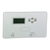
Details the T8002 thermostat's single-stage, programmable control for 24 Vac systems.

Mercury Disposal Notice

Important warning regarding the proper disposal of old mercury-containing controls.

Installation Prerequisites and Safety

Emphasizes reading instructions, checking ratings, installer qualification, and hazardous voltage caution.

Location Selection Guidelines

Recommendations for optimal thermostat placement, avoiding environmental influences.

Wallplate and Wiring Installation

Mounting the Wallplate

Step-by-step instructions for securely attaching the wallplate to the wall.

Wiring Best Practices

Advice on wire gauge, compliance with codes, and connection methods for thermostat wiring.

Wiring Diagrams and System Configurations

Typical Wiring Connections

Illustrations of wiring connections to thermostat terminals and restricting wires to shaded areas.

System Hookup Diagrams

Visual guides for single and two-transformer heat-cool system hookups.

System Hookups and Unit Installation

Heat Pump System Hookup

Diagram illustrating the hookup for a single-stage heat pump system.

Fan Operation Switch

Guide for setting the fan operation (fuel) switch based on system type.

Mounting the Thermostat Unit

Instructions for attaching the thermostat to the wallplate after wiring.

Battery Installation

Steps for inserting the required AA alkaline batteries required for thermostat operation.

Installer Setup and System Testing

Setting Temperature Units and Cycle Rate

Procedure to configure °F/°C display and select the heat cycle rate.

System Checkout Procedure

Steps to verify the proper functioning of heating and cooling outputs after installation.

Thermostat Operation Settings

Fan and System Switch Configuration

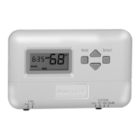
Guide to setting the Fan and System switches for manual control of heating, cooling, and fan.

Time, Day, and Operational Checkout

Setting Current Time and Day

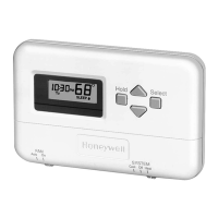
Instructions for inputting the current time and day of the week.

Preprogrammed Settings Overview

Information on default time and temperature settings for different periods.

Heating and Cooling Checkout

Procedures to test heating and cooling system response to thermostat commands.

Final System Checks

Fan Operation Test

Verifying continuous and auto fan operation by adjusting the Fan switch.

Related product manuals