X-XX UL
INSTALLATION INSTRUCTIONS
®U.S. Registered Trademark
Copyright © 2002 Honeywell • • All Rights Reserved
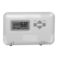
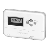
T8011R
Programmable Heat Pump Thermostat
APPLICATION
The T8011R Heat Pump Thermostat provides 24 Vac
control of a two-stage heating and one-stage cooling heat
pump system with manual changeover from heat to cool.
First stage heating and cooling cycle rates are fixed at 3
cph. Second stage heating cycle rate is selectable at
3, 4, 5, 6, 9 or 12 cph. Temperature indication can be set
for °F or °C.
The T8011R Heat Pump Thermostat is powered directly
from the system transformer. Setpoints are held perma-
nently in memory and retained during power outages.
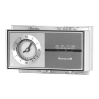
The T8011R TRADELINE® model includes a thermostat,
wallplate and owner’s guide. A 7 3/8 in. (188 mm) x 5 3/4
in. (146 mm) decorator cover plate (for covering wall
marks) is available separately. Order Honeywell part no.
209649A (taupe) or part no. 209649B (white).
MERCURY NOTICE
If this control is replacing a control that contains
mercury in a sealed tube, do not place your old
control in the trash. Dispose of it properly.
Contact your local waste management authority for
instructions regarding recycling and the proper
disposal of a control.
INSTALLATION
When Installing this Product…
1. Read these instructions carefully. Failure to follow
them could damage the product or cause a hazard-
ous condition.
2. Check the ratings given in the instructions and on
the product to make sure the product is suitable for
your application.
3. Installer must be a trained, experienced service
technician.
4. After installation is complete, check out product
operation as provided in these instructions.
CAUTION
Hazardous Voltage
Can damage heating/cooling system.
Disconnect power at furnace or main breaker/fuse
box.
Location
Install the thermostat about 5 ft (1.5m) above the floor in
an area with good air circulation at average temperature.
See Fig. 1. Do not install the thermostat where it can be
affected by:
— drafts or dead spots behind doors and in corners.
— hot or cold air from ducts.
— radiant heat from the sun or appliances.
— concealed pipes and chimneys.
— unheated (uncooled) areas such as an outside wall
behind the thermostat.
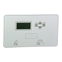
Mounting Wallplate to Wall
IMPORTANT
Level for appearance only. The thermostat
functions normally even when not level.
Mount wallplate and the T8011R with the screws provided
(see Fig. 2) as follows:
1. Place the wallplate at the desired location on the
wall.
2. Pull the thermostat wire through the wallplate
entrance hole.
3. Fasten the wallplate to the wall using the anchors
and screws provided.
4. After wiring the wallplate, plug the hole with non-
flammable insulation to prevent drafts from affecting
the thermostat; see Wiring section.
Table 1. Description of T8011R Thermostats.
Model System Changeover System Selection Fan Selection Powering Method
T8011R Heat Pump Manual Cool-Off-Heat-Em. Ht. Auto-On Hardwired
69-1435-1